-
ADS7057 14ビット、2.5MSPS、差動入力、小型低消費電力SAR ADC
- 1 特長
- 2 アプリケーション
- 3 概要
- 4 改訂履歴
- 5 Pin Configuration and Functions
- 6 Specifications
- 7 Parameter Measurement Information
- 8 Detailed Description
- 9 Application and Implementation
- 10Power Supply Recommendations
- 11Layout
- 12デバイスおよびドキュメントのサポート
- 13メカニカル、パッケージ、および注文情報
- 重要なお知らせ
パッケージ・オプション
メカニカル・データ(パッケージ|ピン)
- RUG|8
サーマルパッド・メカニカル・データ
- RUG|8
発注情報
ADS7057 14ビット、2.5MSPS、差動入力、小型低消費電力SAR ADC
1 特長
- 2.5MSPSのスループット
- 小型パッケージ・サイズ:
- X2QFN-8パッケージ(1.5mm×1.5mm)
- 完全差動入力範囲: ±AVDD
- 広い動作範囲:
- AVDD: 2.35V~3.6V
- DVDD: 1.65V~3.6V (AVDDとは独立)
- 温度範囲: -40℃~+125℃
- 優れた性能:
- 14ビットNMC DNL、±0.9 LSB INL
- 79.5dB SINAD (2kHz時)
- 77dB SINAD (1MHz時)
- 低消費電力:
- 3.6mW (2.5MSPS、3.3V AVDD時)
- 160µW (100kSPS、3.3V AVDD時)
- 82µW (100kSPS、2.5V AVDD時)
- オフセット較正機能を搭載
- SPI互換のシリアル・インターフェイス: 60MHz
- JESD8-7A準拠のデジタルI/O
2 アプリケーション
- 光学エンコーダ
- ソナー受信機
- 魚群探知機
- I-Q復調器
- 光ライン・カードおよびモジュール
- サーマル・イメージング ・カメラ
- 超音波流量計
- 携帯ラジオ
3 概要
ADS7057デバイスは、ピン互換の高速、低消費電力、シングル・チャネルの逐次比較レジスタ(SAR)型アナログ/デジタル・コンバータ(ADC)ファミリの製品です。このデバイス・ファミリには複数の分解能、スループット、およびアナログ入力タイプが用意されています(デバイスのリストについてはTable 1を参照)。
ADS7057は14ビット、2.5MSPS SAR ADCで、±AVDDの範囲の完全差動入力をサポートし、AVDDは2.35V~3.6Vの範囲です。
内部オフセット構成機能により、AVDDの範囲と動作温度範囲の全体にわたって、非常に優れたオフセット仕様が維持されます。
このデバイスはSPI互換のシリアル・インターフェイスをサポートし、CSおよびSCLK信号により制御されます。入力信号はCSの立ち下がりエッジでサンプリングされ、変換とシリアル・データ出力にはSCLKが使用されます。このデバイスは広いデジタル電源範囲(1.65V~3.6V)に対応し、各種のホスト・コントローラと直接接続可能です。ADS7057は、通常のDVDD範囲(1.65V~1.95V)について、JESD8-7Aに準拠しています。
ADS7057は、8ピンの小型X2QFNパッケージで供給され、拡張産業用温度範囲(-40℃~+125℃)で動作が規定されています。小さなフォームファクタと非常に低い消費電力から、このデバイスは高速で高分解能のデータ収集を必要とする、容積が制限されたバッテリ駆動のアプリケーションに適しています。
製品情報(1)
| 型番 | パッケージ | 本体サイズ(公称) |
|---|---|---|
| ADS7057 | X2QFN (8) | 1.50mm×1.50mm |
- 利用可能なすべてのパッケージについては、このデータシートの末尾にある注文情報を参照してください。
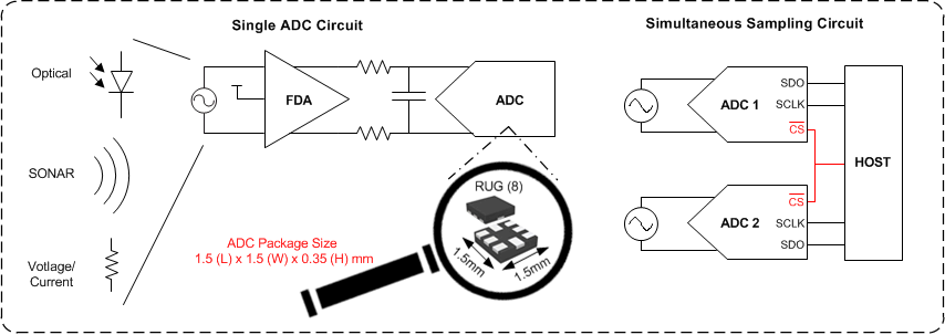
標準アプリケーション
4 改訂履歴
| 日付 | 改訂内容 | 注 |
|---|---|---|
| 2017年12月 | * | 初版 |
5 Pin Configuration and Functions
Pin Functions
| PIN | I/O | DESCRIPTION | |
|---|---|---|---|
| NO. | NAME | ||
| 1 | CS | Digital input | Chip-select signal, active low |
| 2 | SDO | Digital output | Serial data out |
| 3 | SCLK | Digital input | Serial clock |
| 4 | DVDD | Supply | Digital I/O supply voltage |
| 5 | GND | Supply | Ground for power supply, all analog and digital signals are referred to this pin |
| 6 | AVDD | Supply | Analog power-supply input, also provides the reference voltage to the ADC |
| 7 | AINP | Analog input | Analog signal input, positive |
| 8 | AINM | Analog input | Analog signal input, negative |
6 Specifications
6.1 Absolute Maximum Ratings(1)
| MIN | MAX | UNIT | |
|---|---|---|---|
| AVDD to GND | –0.3 | 3.9 | V |
| DVDD to GND | –0.3 | 3.9 | V |
| AINP to GND | –0.3 | AVDD + 0.3 | V |
| AINM to GND | –0.3 | AVDD + 0.3 | V |
| Input current to any pin except supply pins | –10 | 10 | mA |
| Digital input voltage to GND | –0.3 | DVDD + 0.3 | V |
| Storage temperature, Tstg | –60 | 150 | °C |
6.2 ESD Ratings
| VALUE | UNIT | |||
|---|---|---|---|---|
| V(ESD) | Electrostatic discharge | Human body model (HBM), per ANSI/ESDA/JEDEC JS-001(1) | ±2000 | V |
| Charged device model (CDM), per JEDEC specification JESD22-C101(2) | ±1000 | |||
6.3 Recommended Operating Conditions
over operating free-air temperature range (unless otherwise noted)| MIN | NOM | MAX | UNIT | ||
|---|---|---|---|---|---|
| AVDD | Analog supply voltage range | 2.35 | 3.3 | 3.6 | V |
| DVDD | Digital supply voltage range | 1.65 | 1.8 | 3.6 | V |
| TA | Operating free-air temperature | –40 | 25 | 125 | °C |
6.4 Thermal Information
| THERMAL METRIC(1) | ADS7057 | UNIT | |
|---|---|---|---|
| RUG (X2QFN) | |||
| 8 PINS | |||
| RθJA | Junction-to-ambient thermal resistance | 177.5 | °C/W |
| RθJC(top) | Junction-to-case (top) thermal resistance | 51.5 | °C/W |
| RθJB | Junction-to-board thermal resistance | 76.7 | °C/W |
| ψJT | Junction-to-top characterization parameter | 1 | °C/W |
| ψJB | Junction-to-board characterization parameter | 76.7 | °C/W |
| RθJC(bot) | Junction-to-case (bottom) thermal resistance | N/A | °C/W |
6.5 Electrical Characteristics
at AVDD = 3.3 V, DVDD = 1.65 V to 3.6 V, fsample = 2.5 MSPS, and VCM = 1.65 V (unless otherwise noted); minimum and maximum values for TA = –40°C to +125°C; typical values at TA = 25°C| PARAMETER | TEST CONDITIONS | MIN | TYP | MAX | UNIT | |
|---|---|---|---|---|---|---|
| ANALOG INPUT | ||||||
| Full-scale input voltage span(1) | –AVDD | AVDD | V | |||
| Absolute input voltage range | AINP to GND | –0.1 | AVDD + 0.1 | V | ||
| AINM to GND | –0.1 | AVDD + 0.1 | ||||
| Common-mode voltage | (AINP + AINM) / 2 | (AVDD / 2) – 0.1 | (AVDD / 2) + 0.1 | V | ||
| CS | Sampling capacitance | 16 | pF | |||
| SYSTEM PERFORMANCE | ||||||
| Resolution | 14 | Bits | ||||
| NMC | No missing codes | 14 | Bits | |||
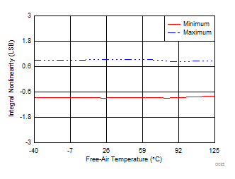
| INL(8) | Integral nonlinearity | –3 | ±0.9 | 3 | LSB(2) | |
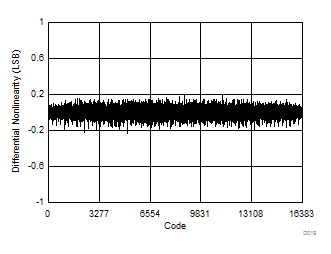
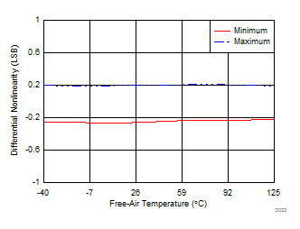
| DNL | Differential nonlinearity | –0.99 | ±0.3 | 1 | LSB | |
| EO(8) | Offset error | After calibration(7) | –6 | ±1 | 6 | LSB |
| dVOS/dT | Offset error drift with temperature | 1.75 | ppm/°C | |||
| EG(8) | Gain error | –0.1 | ±0.01 | 0.1 | %FS | |
| Gain error drift with temperature | 0.5 | ppm/°C | ||||
| SAMPLING DYNAMICS | ||||||
| tCONV | Conversion time | 18 × tSCLK | ns | |||
| tACQ | Acquisition time | 95 | ns | |||
| fSAMPLE | Maximum throughput rate | 60-MHz SCLK, AVDD = 2.35 V to 3.6 V | 2.5 | MHz | ||
| Aperture delay | 3 | ns | ||||
| Aperture jitter, RMS | 12 | ps | ||||
| DYNAMIC CHARACTERISTICS | ||||||
| SNR | Signal-to-noise ratio(4) | AVDD = 3.3 V, fIN = 2 kHz | 76 | 79.6 | dB | |
| AVDD = 2.5 V, fIN = 2 kHz | 78.5 | |||||
| THD | Total harmonic distortion(4)(3) | fIN = 2 kHz | –92 | dB | ||
| fIN = 500 kHz | –90.4 | |||||
| fIN = 1000 kHz | –90.3 | |||||
| SINAD | Signal-to-noise and distortion(4) | fIN = 2 kHz | 76 | 79.3 | dB | |
| fIN = 500 kHz | 78.1 | |||||
| fIN = 1000 kHz | 77.1 | |||||
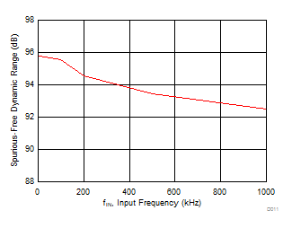
| SFDR | Spurious-free dynamic range(4) | fIN = 2 kHz | 95 | dB | ||
| fIN = 500 kHz | 93.4 | |||||
| fIN = 1000 kHz | 92.4 | |||||
| BW(fp) | Full-power bandwidth | At –3 dB | 200 | MHz | ||
| DIGITAL INPUT/OUTPUT (CMOS Logic Family) | ||||||
| VIH | High-level input voltage(5) | 0.65 DVDD | DVDD + 0.3 | V | ||
| VIL | Low-level input voltage(5) | –0.3 | 0.35 DVDD | V | ||
| VOH | High-level output voltage(5) | At Isource = 500 µA | 0.8 DVDD | DVDD | V | |
| At Isource = 2 mA | DVDD – 0.45 | DVDD | ||||
| VOL | Low-level output voltage(5) | At Isink = 500 µA | 0 | 0.2 DVDD | V | |
| At Isink = 2 mA | 0 | 0.45 | ||||
| POWER-SUPPLY REQUIREMENTS | ||||||
| AVDD | Analog supply voltage | 2.35 | 3 | 3.6 | V | |
| DVDD | Digital I/O supply voltage | 1.65 | 3 | 3.6 | V | |
| IAVDD | Analog supply current | AVDD = 3.3 V, fSAMPLE = 2.5 MSPS | 1100 | 1400 | µA | |
| AVDD = 3.3 V, fSAMPLE = 100 kSPS | 47 | 56 | ||||
| AVDD = 3.3 V, fSAMPLE = 10 kSPS | 5 | |||||
| AVDD = 2.5 V, fSAMPLE = 2.5 MSPS | 820 | |||||
| Static current with CS and SCLK high | 0.02 | |||||
| IDVDD | Digital supply current | DVDD = 1.8 V, CSDO = 20 pF, output code = 2AAAh(6) |
630 | µA | ||
| DVDD = 1.8 V, static current with CS and SCLK high | 0.01 | |||||
6.6 Timing Requirements
all specifications are at AVDD = 2.35 V to 3.6 V, DVDD = 1.65 V to 3.6 V, and CLOAD-SDO = 20 pF (unless otherwise noted); minimum and maximum values for TA = –40°C to +125°C; typical values at TA = 25°C| MIN | TYP | MAX | UNIT | ||
|---|---|---|---|---|---|
| tCLK | Time period of SCLK | 16.66 | ns | ||
| tsu_CSCK | Setup time: CS falling edge to SCLK falling edge | 7 | ns | ||
| tht_CKCS | Hold time: SCLK rising edge to CS rising edge | 8 | ns | ||
| tph_CK | SCLK high time | 0.45 | 0.55 | tSCLK | |
| tpl_CK | SCLK low time | 0.45 | 0.55 | tSCLK | |
| tph_CS | CS high time | 15 | ns | ||
6.7 Switching Characteristics
all specifications are at AVDD = 2.35 V to 3.6 V, DVDD = 1.65 V to 3.6 V, and CLOAD-SDO = 20 pF (unless otherwise noted); minimum and maximum values for TA = –40°C to +125°C; typical values at TA = 25°C| PARAMETER | TEST CONDITIONS | MIN | TYP | MAX | UNIT | |
|---|---|---|---|---|---|---|
| tCYCLE(1) | Cycle time | 400 | ns | |||
| tCONV | Conversion time | 18 × tSCLK | ns | |||
| tden_CSDO | Delay time: CS falling edge to data enable | 6.5 | ns | |||
| td_CKDO | Delay time: SCLK rising edge to (next) data valid on SDO | 10 | ns | |||
| tht_CKDO | SCLK rising edge to current data invalid | 2.5 | ns | |||
| tdz_CSDO | Delay time: CS rising edge to SDO going to tri-state | 5.5 | ns | |||
 Figure 1. Serial Transfer Frame
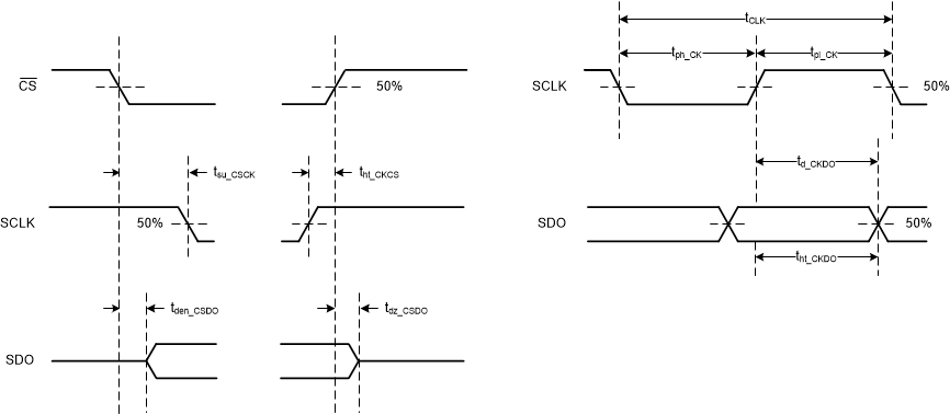 Figure 2. Timing Specifications
6.8 Typical Characteristics
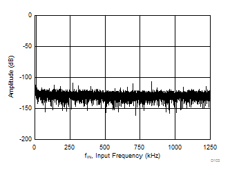
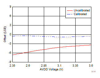
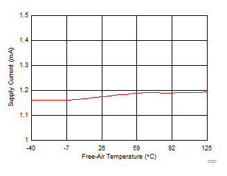
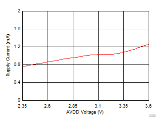
at TA = 25°C, AVDD = 3.3 V, DVDD = 1.8 V, fIN = 2 kHz, and fsample = 2.5 MSPS (unless otherwise noted)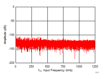
| SNR = 80.1 dB, THD = –96.6 dB, ENOB = 12.9 bits |
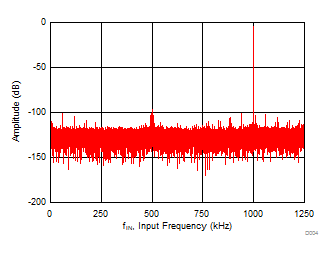
| SNR = 76.8dB, THD = –89.1 dB, fIN = 1000 kHz |
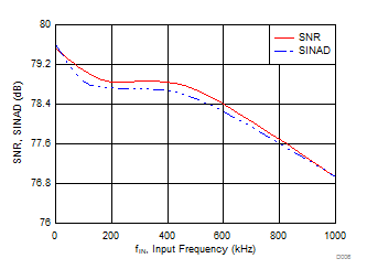
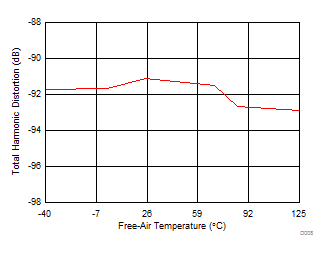
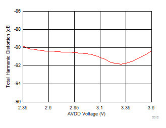
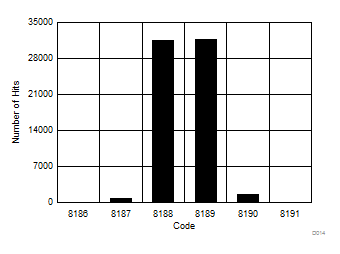
| VIN = 0 (differential) |
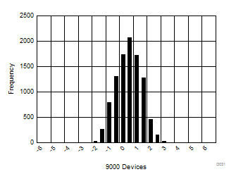
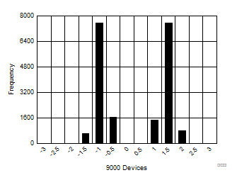
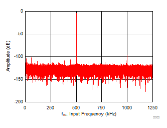
| SNR = 78.7 dB, THD = –89.1 dB, fIN = 500 kHz |
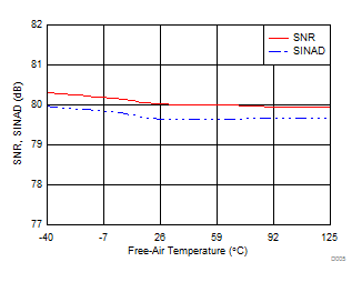
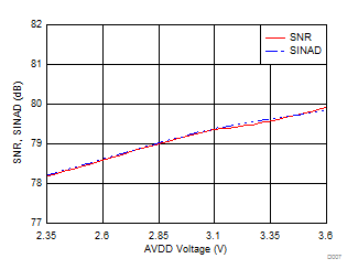
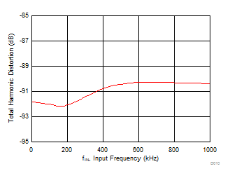
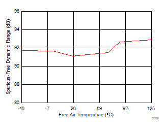
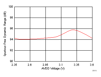
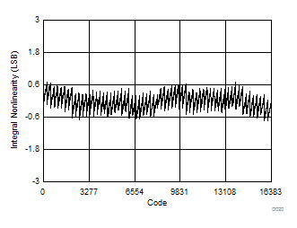
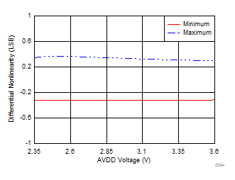
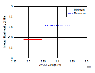
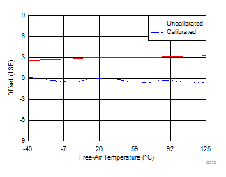
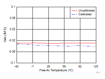
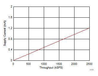
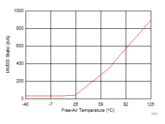
| CS = DVDD |
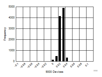
7 Parameter Measurement Information
7.1 Digital Voltage Levels
The device complies with the JESD8-7A standard for DVDD from 1.65 V to 1.95 V. Figure 32 shows voltage levels for the digital input and output pins.
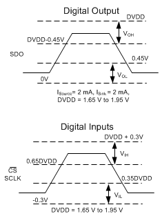 Figure 32. Digital Voltage Levels as per the JESD8-7A Standard
8 Detailed Description
8.1 Overview
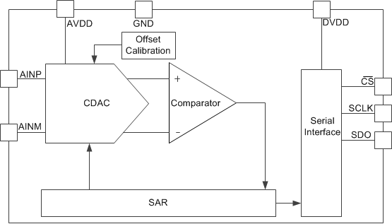
The ADS7057 device belongs to a family of pin-to-pin compatible, high-speed, low-power, single-channel successive-approximation register (SAR) type analog-to-digital converters (ADCs). The device family includes multiple resolutions, throughputs, and analog input variants (see Table 1 for a list of devices).
The ADS7057 is a 14-bit, 2.5-MSPS SAR ADC that supports fully-differential inputs in the range of ±AVDD, for AVDD in the range of 2.35 V to 3.6 V (see the Analog Input section for details on the analog input pins).
The internal offset calibration feature (see the OFFCAL State section) maintains excellent offset specifications over the entire AVDD and temperature operating range.
The device supports an SPI-compatible serial interface that is controlled by the CS and SCLK signals. The input signal is sampled with the CS falling edge and SCLK is used for both, conversion and serial data output (see the Device Functional Modes section, Timing Requirements table, and Switching Characteristics table).
The device supports a wide digital supply range (1.65 V to 3.6 V), enabling direct interfacing to a variety of host controllers. The ADS7057 complies with the JESD8-7A standard (see the Digital Voltage Levels section) for a normal DVDD range (1.65 V to 1.95 V).
The ADS7057 is available in an 8-pin, small, X2QFN package (see the メカニカル、パッケージ、および注文情報 section for more details) and is specified over the extended industrial temperature range (–40°C to +125°C).
The small form-factor and extremely-low power consumption make this device suitable for space-constrained and battery-powered applications that require high-speed, high-resolution data acquisition (see the Application Information section).
8.2 Functional Block Diagram
8.3 Feature Description
8.3.1 Product Family
The devices listed in Table 1 are all part of the same pin-to-pin compatible, high-speed, low-power, single-channel SAR ADC family. This device family includes multiple different ADC resolutions, throughputs, and analog input types to allow for greater flexibility in the end system. Devices in the same package are pin-compatible to offer a scalable family of devices for varying levels of end-system performance. The ADCs with device numbers ending in -Q1 are also AEC-Q100 qualified for automotive applications.
Table 1. Device Family Comparison
| DEVICE NUMBER | RESOLUTION (Bits) | THROUGHPUT (MSPS) | INPUT TYPE | PACKAGES(1) |
|---|---|---|---|---|
| ADS7040 | 8 | 1 | Single-ended | X2QFN (8): 1.5 mm × 1.5 mm VSSOP (8): 2.0 mm × 3.1 mm |
| ADS7041 | 10 | 1 | Single-ended | X2QFN (8): 1.5 mm × 1.5 mm VSSOP (8): 2.0 mm × 3.1 mm |
| ADS7042 | 12 | 1 | Single-ended | X2QFN (8): 1.5 mm × 1.5 mm VSSOP (8): 2.0 mm × 3.1 mm |
| ADS7043 | 12 | 1 | Pseudo-differential | X2QFN (8): 1.5 mm × 1.5 mm VSSOP (8): 2.0 mm × 3.1 mm |
| ADS7044 | 12 | 1 | Fully-differential | X2QFN (8): 1.5 mm × 1.5 mm VSSOP (8): 2.0 mm × 3.1 mm |
| ADS7029-Q1 | 8 | 2 | Single-ended | VSSOP (8): 2.0 mm × 3.1 mm |
| ADS7039-Q1 | 10 | 2 | Single-ended | VSSOP (8): 2.0 mm × 3.1 mm |
| ADS7049-Q1 | 12 | 2 | Single-ended | VSSOP (8): 2.0 mm × 3.1 mm |
| ADS7046 | 12 | 3 | Single-ended | X2QFN (8): 1.5 mm × 1.5 mm |
| ADS7047 | 12 | 3 | Fully-differential | X2QFN (8): 1.5 mm × 1.5 mm |
| ADS7052 | 14 | 1 | Single-ended | X2QFN (8): 1.5 mm × 1.5 mm |
| ADS7054 | 14 | 1 | Fully-differential | X2QFN (8): 1.5 mm × 1.5 mm |
| ADS7056 | 14 | 2.5 | Single-ended | X2QFN (8): 1.5 mm × 1.5 mm |
| ADS7057 | 14 | 2.5 | Fully-differential | X2QFN (8): 1.5 mm × 1.5 mm |
8.3.2 Analog Input
The device supports a unipolar, fully-differential analog input signal. Figure 33 shows a small-signal equivalent circuit of the sample-and-hold circuit. The sampling switch is represented by a resistance (RS1 and RS2, typically 50 Ω) in series with an ideal switch (SW1 and SW2). The sampling capacitors, CS1 and CS2, are typically 16 pF.
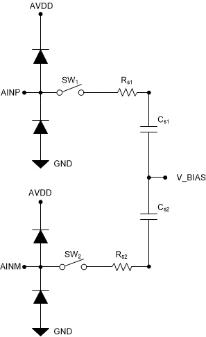 Figure 33. Equivalent Input Circuit for the Sampling Stage
During the acquisition process, both positive and negative inputs are individually sampled on CS1 and CS2, respectively. During the conversion process, the device converts for the voltage difference between the two sampled values: VAINP – VAINM.
Each analog input pin has electrostatic discharge (ESD) protection diodes to AVDD and GND. Keep the analog inputs within the specified range to avoid turning the diodes on.
The full-scale analog input range (FSR) is VFSR = –AVDD to AVDD and the common-mode input voltage is AVDD / 2 ± 0.1 V.
8.3.3 Reference
The device uses the analog supply voltage (AVDD) as the reference voltage for the analog to digital conversion. During the conversion process, the internal capacitors are switched to the AVDD pin as per the successive approximation algorithm. A voltage reference must be selected with low temperature drift, high output current drive and low output impedance. TI recommends a 3.3-µF (CAVDD), low equivalent series resistance (ESR) ceramic capacitor between the AVDD and GND pins. This decoupling capacitor provides the instantaneous charge required by the internal circuit during the conversion process and maintains a stable dc voltage on the AVDD pin.
See the Power Supply Recommendations and Layout Example sections for component recommendations and layout guidelines.
 Figure 34. Reference for the Device
8.3.4 ADC Transfer Function
The device supports a unipolar fully-differential analog input signal. The output is in two's compliment format. Figure 35 and Table 2 show the ideal transfer characteristics for the device.
The least significant bit for the device is given by:
where
- VREF = Voltage applied between the AVDD and GND pins
- N = 14
 Figure 35. Ideal Transfer Characteristics
Table 2. Transfer Characteristics
| INPUT VOLTAGE (AINP – AINM) | CODE | DESCRIPTION | IDEAL OUTPUT CODE (Hex) |
|---|---|---|---|
| ≤ –(VREF – 1 LSB) | NFSC | Negative full-scale code | 2000 |
| –(VREF – 1 LSB) to –(VREF – 2 LSB) | NFSC + 1 | — | 2001 |
| 0 LSB to 1 LSB | MC | Mid code | 0000 |
| 1 LSB to 2 LSB | MC + 1 | — | 0001 |
| ≥ VREF – 1 LSB | PFSC | Positive full-scale code | 1FFF |
8.4 Device Functional Modes
The device supports a simple, SPI-compatible interface to the external host. On power-up, the device is in the ACQ state. The CS signal defines one conversion and serial data transfer frame. A frame starts with a CS falling edge and ends with a CS rising edge. The SDO pin is tri-stated when CS is high. With CS low, the clock provided on the SCLK pin is used for conversion and data transfer. Output data are available on the SDO pin.
As shown in Figure 36, the device supports three functional states: acquisition (ACQ), conversion (CNV), and offset calibration (OFFCAL). The device status depends on the CS and SCLK signals provided by the host controller.
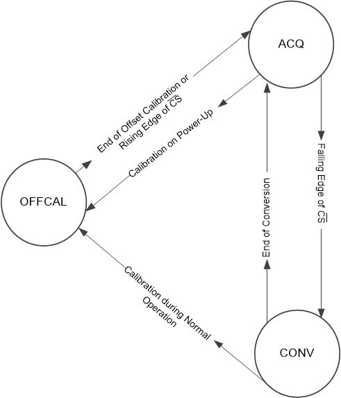 Figure 36. Functional State Diagram
8.4.1 ACQ State
In the ACQ state, switches SW1 and SW2 connected to the analog input pins close and the device acquires the analog input signal on CS1 and CS2. The device enters ACQ state at power-up, at the end of every conversion, and after completing the offset calibration. A CS falling edge takes the device from the ACQ state to the CNV state.
The device consumes extremely low power from the AVDD and DVDD power supplies when in ACQ state.
8.4.2 CNV State
In the CNV state, the device uses the external clock to convert the sampled analog input signal to an equivalent digital code as per the transfer function illustrated in Figure 35. The conversion process requires a minimum of 18 SCLK falling edges to be provided within the frame. After the end of conversion process, the device automatically moves from the CNV state to the ACQ state. For acquisition of the next sample, a minimum time of tACQ must be provided.
Figure 37 shows a detailed timing diagram for the serial interface. In the first serial transfer frame after power-up, the device provides the first data as all zeros. In any frame, the clocks provided on the SCLK pin are also used to transfer the output data for the previous conversion. A leading 0 is output on the SDO pin on the CS falling edge. The most significant bit (MSB) of the output data is launched on the SDO pin on the rising edge after the first SCLK falling edge. Subsequent output bits are launched on the subsequent rising edges provided on SCLK. When all 14 output bits are shifted out, the device outputs 0's on the subsequent SCLK rising edges. The device enters the ACQ state after 18 clocks and a minimum time of tACQ must be provided for acquiring the next sample. If the device is provided with less than 18 SCLK falling edges in the present serial transfer frame, the device provides an invalid conversion result in the next serial transfer frame.
 Figure 37. Serial Interface Timing Diagram
8.4.3 OFFCAL State
In the offset calibration (OFFCAL) state, the sampling capacitors are disconnected from the analog input pins (AINP and AINM) and the device calibrates and corrects for any internal offset errors. The offset calibration is effective for all subsequent conversions until the device is powered off. An offset calibration cycle is recommended at power-up and whenever there is a significant change in the operating conditions for the device (such as in the AVDD voltage and operating temperature).
The host controller must provide a serial transfer frame as described in Figure 38 or in Figure 39 to enter the OFFCAL state.
8.4.3.1 Offset Calibration on Power-Up
On power-up, the host must provide 24 SCLKs in the first serial transfer to enter the OFFCAL state. The device provides 0's on SDO during offset calibration. For acquisition of the next sample, a minimum time of tACQ must be provided.
If the host controller starts the offset calibration process but then pulls the CS pin high before providing 24 SCLKs, then the offset calibration process is aborted and the device enters the ACQ state. Figure 38 and Table 3 provide the timing for offset calibration on power-up.
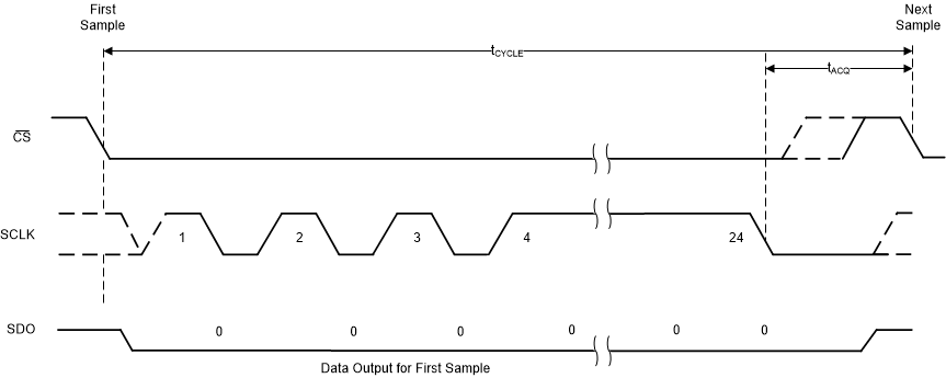 Figure 38. Timing for Offset Calibration on Power-Up
Table 3. Timing Specifications for Offset Calibration on Power-Up(1)
| MIN | TYP | MAX | UNIT | ||
|---|---|---|---|---|---|
| tcycle | Cycle time for offset calibration on power-up | 24 × tCLK + tACQ | ns | ||
| tACQ | Acquisition time | 95 | ns | ||
| fSCLK | Frequency of SCLK | 60 | MHz | ||
8.4.3.2 Offset Calibration During Normal Operation
During normal operation, the host must provide 64 SCLKs in the serial transfer frame to enter the OFFCAL state. The device provides the conversion result for the previous sample during the first 18 SCLKs and 0's on SDO for the rest of the SCLKs in the serial transfer frame. For acquisition of the next sample, a minimum time of tACQ must be provided.
If the host controller provides more than 18 SCLKs but pulls the CS high before providing 64 SCLKs, then the offset calibration process is aborted and the device enters the ACQ state. Figure 39 and Table 4 provide the timing for offset calibration during normal operation.
 Figure 39. Timing for Offset Calibration During Normal Operation
Table 4. Timing Specifications for Offset Calibration During Normal Operation(1)
| MIN | TYP | MAX | UNIT | ||
|---|---|---|---|---|---|
| tcycle | Cycle time for offset calibration on power-up | 64 × tCLK + tACQ | ns | ||
| tACQ | Acquisition time | 95 | ns | ||
| fSCLK | Frequency of SCLK | 60 | MHz | ||
9 Application and Implementation
NOTE
Information in the following applications sections is not part of the TI component specification, and TI does not warrant its accuracy or completeness. TI’s customers are responsible for determining suitability of components for their purposes. Customers should validate and test their design implementation to confirm system functionality.
9.1 Application Information
The two primary supporting circuits required to maximize the performance of a high-precision, successive approximation register (SAR) analog-to-digital converter (ADC) are the input driver and the reference driver circuits. This section details some general principles for designing the input driver circuit, reference driver circuit, and provides typical application circuits designed for the device.
9.2 Typical Applications
9.2.1 2-Channel, Simultaneous Sampling Data Acquisition Using the ADS7057
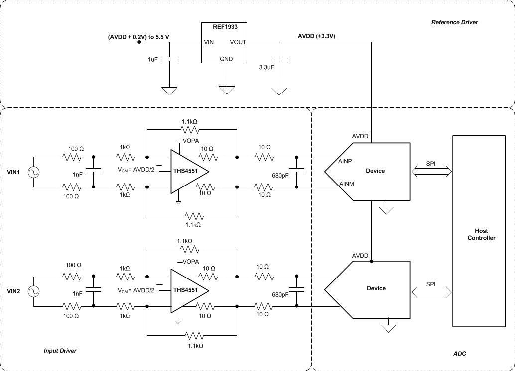 Figure 40. 2-Channel, Simultaneous-Sampling Data Acquisition (DAQ) Circuit Using the ADS7057
9.2.1.1 Design Requirements
The goal of the circuit shown in Figure 40 is to design a two-channel, simultaneous-sampling data acquisition (DAQ) circuit based on the ADS7057 with an SNR greater than 79 dB and a THD less than –85 dB for input frequencies from 2 kHz to 50 kHz at a throughput of 2.5 MSPS. This simultaneous-sampling scheme is typically used in motor sine and cosine (sin-cos) encoders, resolvers, fish finders, sonar, and I-Q demodulation.
9.2.1.2 Detailed Design Procedure
The input driver circuit for a high-precision ADC mainly consists of two parts: a driving amplifier and charge kickback filter. Careful design of the front-end circuit is critical to meet the linearity and noise performance of a high-precision ADC.
9.2.1.2.1 Low Distortion Charge Kickback Filter Design
Figure 41 shows the input circuit of a typical SAR ADC. During the acquisition phase, the SW switch closes and connects the sampling capacitor (CSH) to the input driver circuit. This action introduces a transient on the input pins of the SAR ADC. An ideal amplifier with 0 Ω of output impedance and infinite current drive can settle this transient in zero time. For a real amplifier with non-zero output impedance and finite drive strength, this switched capacitor load can create stability issues.
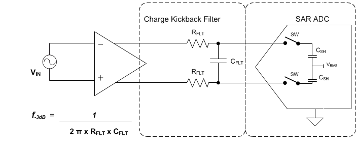 Figure 41. Input Sample-and-Hold Circuit for a Typical SAR ADC
For ac signals, the filter bandwidth must be kept low to band-limit the noise fed into the ADC input, thereby increasing the signal-to-noise ratio (SNR) of the system. Besides filtering the noise from the front-end drive circuitry, the RC filter also helps attenuate the sampling charge injection from the switched-capacitor input stage of the ADC. A filter capacitor, CFLT, is connected across the ADC inputs. This capacitor helps reduce the sampling charge injection and provides a charge bucket to quickly charge the internal sample-and-hold capacitors during the acquisition process. As a rule of thumb, the value of this capacitor is at least 20 times the specified value of the ADC sampling capacitance. For this device, the input sampling capacitance is equal to 16 pF. Thus, the value of CFLT is greater than 320 pF. Select a COG- or NPO-type capacitor because these capacitor types have a high-Q, low-temperature coefficient, and stable electrical characteristics under varying voltages, frequency, and time.
Driving capacitive loads can degrade the phase margin of the input amplifiers, thus making the amplifier marginally unstable. To avoid amplifier stability issues, series isolation resistors (RFLT) are used at the output of the amplifiers. A higher value of RFLT is helpful from the amplifier stability perspective, but adds distortion as a result of interactions with the nonlinear input impedance of the ADC. Distortion increases with source impedance, input signal frequency, and input signal amplitude. Therefore, the selection of RFLT requires balancing the stability and distortion of the design.
9.2.1.2.2 Input Amplifier Selection
The input amplifier bandwidth is typically much higher than the cutoff frequency of the charge kickback filter. Thus, TI strongly recommends performing a SPICE simulation to confirm that the amplifier has more than 40° phase margin with the selected filter. Simulation is critical because even with high-bandwidth amplifiers, some amplifiers can require more bandwidth than others to drive similar filters. To learn more about the SAR ADC input driver design, see the TI Precision Labs training video series.
The THS4551 is selected for its high bandwidth (135 MHz), low total harmonic distortion of –90 dBc at 100 kHz, and ultra-low noise of (3.2 nV/√Hz). The THS4551 is powered up from the power supply (VDD = 5 V and VSS = GND).
9.2.1.2.3 Reference Circuit
The ADS70xx uses the analog supply voltage (AVDD) as the reference voltage for the analog-to-digital conversion. During the conversion process, the internal capacitors are switched to the level of the AVDD pin as per the successive approximation algorithm. A voltage reference must be selected with low temperature drift, high output current drive, and low output impedance. For this application, the REF1933 was selected as the voltage reference and analog power supply for the ADC. The REF1933 has excellent temperature drift performance (25 ppm/°C), good initial accuracy (0.1%), high output drive capability (25 mA), and low quiescent current (360 µA). The REF1933 also provides a bias voltage output of half the reference voltage (VREF / 2) that can be used as the common-mode input for the amplifier.
TI recommends a 3.3-μF (CAVDD), low equivalent series resistance (ESR) ceramic capacitor between the AVDD and GND pins. This decoupling capacitor provides the instantaneous charge required by the internal circuit during the conversion process and maintains a stable dc voltage on the AVDD pin.
9.2.1.3 Application Curves
Figure 42 and Figure 43 provide the measurement results for the circuit described in Figure 40.
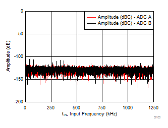
| Device 1 | SNR = 79.7 dB, THD = –90 dB, SINAD = 79.3 dB | ||
| Device 2 | SNR = 79.3 dB, THD = –87 dB, SINAD = 79.1 dB | ||
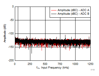
| Device 1 | SNR = 79.2 dB, THD = –87 dB, SINAD = 78.9 dB | ||
| Device 2 | SNR = 78.9 dB, THD = –84 dB, SINAD = 78.1 dB | ||
9.2.2 Improving Precision of Single-Ended Signal Source Measurements Using the ADS7057
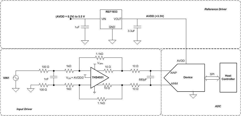 Figure 44. Interfacing Single-Ended Signals with the ADS7057 Using a Single-Ended to Differential
 Front-End
9.2.2.1 Design Requirements
Some applications have sensor or signal inputs that are single ended. In order to increase the dynamic range, linearity, and precision of the system, such single-ended signals are often required to be interfaced with a differential input ADC. The goal of the design shown in Figure 44 is to interface a single-ended input source with the ADS7057 using a single-ended to differential front-end amplifier to achieve an SNR greater than 79 dB and a THD less than –85 dB for input frequencies up to 10 kHz at a throughput of 2.5 MSPS.
9.2.2.2 Detailed Design Procedure
To achieve a SNR greater than 79 dB, the operational amplifier must have high bandwidth in order to settle the input signal within the acquisition time of the ADC. The operational amplifier must have low noise to keep the total system noise below 20% of the input-referred noise of the ADC. For the application circuit shown in Figure 44, the THS4551 is selected for its high bandwidth (135 MHz), low total harmonic distortion of –90 dBc at 100 kHz, and ultra-low noise of (3.2 nV/√Hz). The THS4551 is powered up from the power supply (VDD = 5 V and VSS = GND).
The THS4551 can be used in a single-ended to differential configuration as shown in Figure 44 without any performance degradation. This configuration enables single-ended input signals to be interfaced with differential input SAR ADCs (such as the ADS7057) to achieve higher system-level precision.
For this application, the REF1933 was selected as the voltage reference and analog power supply for the ADC. The REF1933 has excellent temperature drift performance (25 ppm/°C), good initial accuracy (0.1%), high output drive capability (25 mA), and low quiescent current (360 µA). The REF1933 also provides a bias voltage output of half the reference voltage (VREF / 2) that can be used as the common-mode input for the amplifier.
10 Power Supply Recommendations
10.1 AVDD and DVDD Supply Recommendations
The device has two separate power supplies: AVDD and DVDD.
AVDD powers the analog blocks and is also used as the reference voltage for the analog-to-digital conversion. Use a low-noise, low-dropout regulator (LDO) or a discrete reference to supply AVDD (see the Reference and Application Information sections). Always set the AVDD supply to be greater than or equal to the maximum input signal to avoid code saturation. Decouple the AVDD pin to the GND pin with a 3.3-µF ceramic decoupling capacitor.
DVDD is used for the interface circuits. Decouple the DVDD pin to the GND pin with a 1-µF ceramic decoupling capacitor. Figure 46 shows the decoupling recommendations.
 Figure 46. Power-Supply Decoupling
10.2 Optimizing Power Consumed by the Device
In order to best optimize the power consumed by the device, use the following design considerations:
- Keep the analog supply voltage (AVDD) in the specified operating range and equal to the maximum analog input voltage.
- Keep the digital supply voltage (DVDD) in the specified operating range and at the lowest value supported by the host controller.
- Reduce the load capacitance on the SDO output.
- Run the device at the optimum throughput. Power consumption reduces proportionally with the throughput.
10.2.1 Estimating Digital Power Consumption
The current consumption from the DVDD supply depends on the DVDD voltage, the load capacitance on the SDO pin (CLOAD-SDO), and the output code, and can be calculated as:
where
- CLOAD-SDO = Load capacitance on the SDO pin
- V = DVDD supply voltage
- f = Frequency of transitions on the SDO output
The number of transitions on the SDO output depends on the output code, and thus changes with the analog input. The maximum value of f occurs when data output on the SDO change on every SCLK (that is, for output codes of 2AAAh or 1555h). With an output code of 2AAAh or 1555h, f = 17.5 MHz and when CLOAD-SDO = 20 pF and DVDD = 1.8 V, IDVDD = 630 µA.
11 Layout
11.1 Layout Guidelines
Figure 47 shows a typical connection diagram for the ADS7057.
 Figure 47. Typical Connection Diagram
Figure 48 depicts a board layout example for the device for the typical connection diagram in Figure 47. The key considerations for layout are:
- Use a solid ground plane underneath the device and partition the PCB into analog and digital sections
- Avoid crossing digital lines with the analog signal path and keep the analog input signals and the reference input signals away from noise sources.
- The power sources to the device must be clean and well-bypassed. Use CAVDD decoupling capacitors in close proximity to the analog (AVDD) power-supply pin.
- Use a CDVDD decoupling capacitor close to the digital (DVDD) power-supply pin.
- Avoid placing vias between the AVDD and DVDD pins and the bypass capacitors.
- Connect the ground pin to the ground plane using a short, low-impedance path.
- Place the charge kickback filter components close to the device.
Among ceramic surface-mount capacitors, COG (NPO) ceramic capacitors are recommended because these components provide the most stable electrical properties over voltage, frequency, and temperature changes.
11.2 Layout Example
 Figure 48. Example Layout
12 デバイスおよびドキュメントのサポート
12.1 デバイス・サポート
12.1.1 開発サポート
12.2 ドキュメントのサポート
12.2.1 関連資料
関連資料については、以下を参照してください。
入力ドライバ・アンプ(シングル・エンド入力):
- 『OPAx836 超低消費電力、レール・ツー・レール出力、負のレール入力、電圧フィードバック・オペアンプ』
- 『THS403x 100MHz、低ノイズ、高速アンプ』
- 『OPAx365 50MHz、ゼロ・クロスオーバー、低歪み、高CMRR、RRI/O、単一電源オペアンプ』
入力ドライバ・アンプ(完全差動入力):
リファレンス・ドライバ:
類似デバイス:
リファレンス・デザイン:
12.3 ドキュメントの更新通知を受け取る方法
ドキュメントの更新についての通知を受け取るには、ti.comのデバイス製品フォルダを開いてください。右上の隅にある「通知を受け取る」をクリックして登録すると、変更されたすべての製品情報に関するダイジェストを毎週受け取れます。変更の詳細については、修正されたドキュメントに含まれている改訂履歴をご覧ください。
12.4 コミュニティ・リソース
The following links connect to TI community resources. Linked contents are provided "AS IS" by the respective contributors. They do not constitute TI specifications and do not necessarily reflect TI's views; see TI's Terms of Use.
-
TI E2E™オンライン・コミュニティ TIのE2E(Engineer-to-Engineer)コミュニティ。エンジニア間の共同作業を促進するために開設されたものです。e2e.ti.comでは、他のエンジニアに質問し、知識を共有し、アイディアを検討して、問題解決に役立てることができます。
-
設計サポート TIの設計サポート 役に立つE2Eフォーラムや、設計サポート・ツールをすばやく見つけることができます。技術サポート用の連絡先情報も参照できます。
12.5 商標
E2E is a trademark of Texas Instruments.
All other trademarks are the property of their respective owners.
12.6 静電気放電に関する注意事項

すべての集積回路は、適切なESD保護方法を用いて、取扱いと保存を行うようにして下さい。
静電気放電はわずかな性能の低下から完全なデバイスの故障に至るまで、様々な損傷を与えます。高精度の集積回路は、損傷に対して敏感であり、極めてわずかなパラメータの変化により、デバイスに規定された仕様に適合しなくなる場合があります。
12.7 Glossary
SLYZ022 — TI Glossary.
This glossary lists and explains terms, acronyms, and definitions.
13 メカニカル、パッケージ、および注文情報
以降のページには、メカニカル、パッケージ、および注文に関する情報が記載されています。この情報は、そのデバイスについて利用可能な最新のデータです。このデータは予告なく変更されることがあり、ドキュメントが改訂される場合もあります。本データシートのブラウザ版を使用されている場合は、画面左側の説明をご覧ください。


IMPORTANT NOTICE
Texas Instruments Incorporated (TI) reserves the right to make corrections, enhancements, improvements and other changes to its semiconductor products and services per JESD46, latest issue, and to discontinue any product or service per JESD48, latest issue. Buyers should obtain the latest relevant information before placing orders and should verify that such information is current and complete.
TI’s published terms of sale for semiconductor products (http://www.ti.com/sc/docs/stdterms.htm) apply to the sale of packaged integrated circuit products that TI has qualified and released to market. Additional terms may apply to the use or sale of other types of TI products and services.
Reproduction of significant portions of TI information in TI data sheets is permissible only if reproduction is without alteration and is accompanied by all associated warranties, conditions, limitations, and notices. TI is not responsible or liable for such reproduced documentation. Information of third parties may be subject to additional restrictions. Resale of TI products or services with statements different from or beyond the parameters stated by TI for that product or service voids all express and any implied warranties for the associated TI product or service and is an unfair and deceptive business practice. TI is not responsible or liable for any such statements.
Buyers and others who are developing systems that incorporate TI products (collectively, “Designers”) understand and agrees that Designers remain responsible for using their independent analysis, evaluation and judgment in designing their systems and products, and have full and exclusive responsibility to assure the safety of their products and compliance of their products (and of all TI products used in or for such Designers’ products) with all applicable regulations, laws and other applicable requirements. Designers represent that, with respect to their applications, they have all the necessary expertise to create and implement safeguards that (1) anticipate dangerous consequences of failures, (2) monitor failures and their consequences, and (3) lessen the likelihood of failures that might cause harm and take appropriate actions. Designers agree that prior to using or distributing any systems that include TI products, they will thoroughly test such systems and the functionality of such TI products as used in such systems.
TI’s provision of reference designs and any other technical, applications or design advice, quality characterization, reliability data or other information or services does not expand or otherwise alter TI’s applicable published warranties or warranty disclaimers for TI products, and no additional obligations or liabilities arise from TI providing such reference designs or other items.
Designers are authorized to use, copy and modify any individual TI reference design only in connection with the development of end products that include the TI product(s) identified in that reference design. HOWEVER, NO OTHER LICENSE, EXPRESS OR IMPLIED, BY ESTOPPEL OR OTHERWISE TO ANY OTHER TI INTELLECTUAL PROPERTY RIGHT, AND NO LICENSE TO ANY TECHNOLOGY OR INTELLECTUAL PROPERTY RIGHT OF TI OR ANY THIRD PARTY IS GRANTED HEREIN, including but not limited to any patent right, copyright, mask work right, or other intellectual property right relating to any combination, machine, or process in which TI products or services are used. Information published by TI regarding third-party products or services does not constitute a license to use such products or services, or a warranty or endorsement thereof. Use of the reference design or other items described above may require a license from a third party under the patents or other intellectual property of the third party, or a license from TI under the patents or other intellectual property of TI.
TI REFERENCE DESIGNS AND OTHER ITEMS DESCRIBED ABOVE ARE PROVIDED “AS IS” AND WITH ALL FAULTS. TI DISCLAIMS ALL OTHER WARRANTIES OR REPRESENTATIONS, EXPRESS OR IMPLIED, REGARDING THE REFERENCE DESIGNS OR USE OF THE REFERENCE DESIGNS, INCLUDING BUT NOT LIMITED TO ACCURACY OR COMPLETENESS, TITLE, ANY EPIDEMIC FAILURE WARRANTY AND ANY IMPLIED WARRANTIES OF MERCHANTABILITY, FITNESS FOR A PARTICULAR PURPOSE, AND NON-INFRINGEMENT OF ANY THIRD PARTY INTELLECTUAL PROPERTY RIGHTS.
TI SHALL NOT BE LIABLE FOR AND SHALL NOT DEFEND OR INDEMNIFY DESIGNERS AGAINST ANY CLAIM, INCLUDING BUT NOT LIMITED TO ANY INFRINGEMENT CLAIM THAT RELATES TO OR IS BASED ON ANY COMBINATION OF PRODUCTS AS DESCRIBED IN A TI REFERENCE DESIGN OR OTHERWISE. IN NO EVENT SHALL TI BE LIABLE FOR ANY ACTUAL, DIRECT, SPECIAL, COLLATERAL, INDIRECT, PUNITIVE, INCIDENTAL, CONSEQUENTIAL OR EXEMPLARY DAMAGES IN CONNECTION WITH OR ARISING OUT OF THE REFERENCE DESIGNS OR USE OF THE REFERENCE DESIGNS, AND REGARDLESS OF WHETHER TI HAS BEEN ADVISED OF THE POSSIBILITY OF SUCH DAMAGES.
Unless TI has explicitly designated an individual product as meeting the requirements of a particular industry standard (e.g., ISO/TS 16949 and ISO 26262), TI is not responsible for any failure to meet such industry standard requirements.
Where TI specifically promotes products as facilitating functional safety or as compliant with industry functional safety standards, such products are intended to help enable customers to design and create their own applications that meet applicable functional safety standards and requirements. Using products in an application does not by itself establish any safety features in the application. Designers must ensure compliance with safety-related requirements and standards applicable to their applications. Designer may not use any TI products in life-critical medical equipment unless authorized officers of the parties have executed a special contract specifically governing such use. Life-critical medical equipment is medical equipment where failure of such equipment would cause serious bodily injury or death (e.g., life support, pacemakers, defibrillators, heart pumps, neurostimulators, and implantables). Such equipment includes, without limitation, all medical devices identified by the U.S. Food and Drug Administration as Class III devices and equivalent classifications outside the U.S.
TI may expressly designate certain products as completing a particular qualification (e.g., Q100, Military Grade, or Enhanced Product). Designers agree that it has the necessary expertise to select the product with the appropriate qualification designation for their applications and that proper product selection is at Designers’ own risk. Designers are solely responsible for compliance with all legal and regulatory requirements in connection with such selection.
Designer will fully indemnify TI and its representatives against any damages, costs, losses, and/or liabilities arising out of Designer’s non-compliance with the terms and provisions of this Notice.
IMPORTANT NOTICE
| Mailing Address: Texas Instruments, Post Office Box 655303, Dallas, Texas 75265 Copyright © 2017, Texas Instruments Incorporated |
