JAJSCU6B december 2016 – march 2021 ADS8661 , ADS8665
PRODUCTION DATA
- 1
- 1 特長
- 2 アプリケーション
- 3 概要
- 4 Revision History
- 5 Pin Configuration and Functions
-
6 Specifications
- 6.1 Absolute Maximum Ratings
- 6.2 ESD Ratings
- 6.3 Recommended Operating Conditions
- 6.4 Thermal Information
- 6.5 Electrical Characteristics
- 6.6 Timing Requirements: Conversion Cycle
- 6.7 Timing Requirements: Asynchronous Reset
- 6.8 Timing Requirements: SPI-Compatible Serial Interface
- 6.9 Timing Requirements: Source-Synchronous Serial Interface (External Clock)
- 6.10 Timing Requirements: Source-Synchronous Serial Interface (Internal Clock)
- 6.11 Timing Diagrams
- 6.12 Typical Characteristics
-
7 Detailed Description
- 7.1 Overview
- 7.2 Functional Block Diagram
- 7.3 Feature Description
- 7.4 Device Functional Modes
- 7.5 Programming
- 7.6
Register Maps
- 7.6.1
Device Configuration and Register Maps
- 7.6.1.1 DEVICE_ID_REG Register (address = 00h)
- 7.6.1.2 RST_PWRCTL_REG Register (address = 04h)
- 7.6.1.3 SDI_CTL_REG Register (address = 08h)
- 7.6.1.4 SDO_CTL_REG Register (address = 0Ch)
- 7.6.1.5 DATAOUT_CTL_REG Register (address = 10h)
- 7.6.1.6 RANGE_SEL_REG Register (address = 14h)
- 7.6.1.7 ALARM_REG Register (address = 20h)
- 7.6.1.8 ALARM_H_TH_REG Register (address = 24h)
- 7.6.1.9 ALARM_L_TH_REG Register (address = 28h)
- 7.6.1
Device Configuration and Register Maps
- 8 Application and Implementation
- 9 Power Supply Recommendations
- 10Layout
- 11Device and Documentation Support
- Mechanical, Packaging, and Orderable Information
3 概要
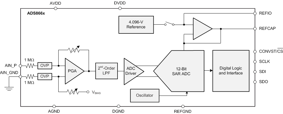
ADS8661 と ADS8665 は、逐次比較型 (SAR) A/D コンバータ (ADC) を使った統合型データ・アクイジション・システム・ファミリの製品です。これらのデバイスは高速、高精度の SAR ADC、統合アナログ・フロントエンド (AFE) 入力ドライバ回路、最大 ±20V の過電圧保護回路、温度ドリフトの非常に低いオンチップの 4.096V 基準電圧を搭載しています。
これらのデバイスは 1 つの 5V アナログ電源で動作します。しかし、±12.288V、±6.144V、±10.24V、±5.12V、±2.56V の真のバイポーラ入力範囲と、0V~12.288V、0V~10.24V、0V~6.144V、0V~5.12V のユニポーラ入力範囲をサポートしています。高い DC 精度を保証するため、ゲインおよびオフセット誤差は、各入力範囲の規定値内に正確に調整されています。入力範囲は、デバイスの内部レジスタに対するソフトウェア・プログラミングにより選択されます。これらのデバイスは、選択した入力範囲にかかわらず、高い抵抗性入力インピーダンス (≥ 1MΩ) を実現しています。
内蔵の multiSPI デジタル・インターフェイスは、従来の SPI プロトコルと下位互換性があります。さらに、設定可能な機能により、広範なホスト・コントローラとの接続が簡素化されます。
製品情報(1)
| 部品番号 | パッケージ | 本体サイズ (公称) |
|---|---|---|
| ADS866x | TSSOP (16) | 5.00mm × 4.40mm |
(1) 利用可能なすべてのパッケージについては、このデータシートの末尾にある注文情報を参照してください。
 ブロック図
ブロック図