-
ADS9120 16ビット、2.5MSPS、15.5mW、拡張パフォーマンス機能搭載のSAR ADC
- 1 特長
- 2 アプリケーション
- 3 概要
- 4 改訂履歴
- 5 Pin Configuration and Functions
-
6 Specifications
- 6.1 Absolute Maximum Ratings
- 6.2 ESD Ratings
- 6.3 Recommended Operating Conditions
- 6.4 Thermal Information
- 6.5 Electrical Characteristics
- 6.6 Timing Requirements: Conversion Cycle
- 6.7 Timing Requirements: Asynchronous Reset, NAP, and PD
- 6.8 Timing Requirements: SPI-Compatible Serial Interface
- 6.9 Timing Requirements: Source-Synchronous Serial Interface (External Clock)
- 6.10 Timing Requirements: Source-Synchronous Serial Interface (Internal Clock)
- 6.11 Typical Characteristics
-
7 Detailed Description
- 7.1 Overview
- 7.2 Functional Block Diagram
- 7.3 Feature Description
- 7.4 Device Functional Modes
- 7.5
Programming
- 7.5.1 Data Transfer Frame
- 7.5.2 Interleaving Conversion Cycles and Data Transfer Frames
- 7.5.3 Data Transfer Protocols
- 7.5.4 Device Setup
- 7.6 Register Maps
- 8 Application and Implementation
- 9 Power-Supply Recommendations
- 10Layout
- 11デバイスおよびドキュメントのサポート
- 12メカニカル、パッケージ、および注文情報
- 重要なお知らせ
パッケージ・オプション
メカニカル・データ(パッケージ|ピン)
- RGE|24
サーマルパッド・メカニカル・データ
- RGE|24
発注情報
DATA SHEET
ADS9120 16ビット、2.5MSPS、15.5mW、拡張パフォーマンス機能搭載のSAR ADC
このリソースの元の言語は英語です。 翻訳は概要を便宜的に提供するもので、自動化ツール (機械翻訳) を使用していることがあり、TI では翻訳の正確性および妥当性につきましては一切保証いたしません。 実際の設計などの前には、ti.com で必ず最新の英語版をご参照くださいますようお願いいたします。
1 特長
- サンプリング・レート: 2.5MSPS
- レイテンシなしの出力
- 優れたDCおよびAC性能
- INL: ±0.25 LSB
- DNL: ±0.6 LSB
- SNR: 96 dB、THD: -118dB
- 広い入力電圧範囲
- ユニポーラ差動入力電圧範囲: ±VREF
- VREF入力電圧範囲: 2.5V~5V
AVDDに対して独立
- 低消費電力
- 2.5MSPSで9mW (AVDDのみ)
- 2.5MSPSで15.5mW (合計)
- 柔軟な低消費電力モードにより、スループットに応じて電力を調整可能
- Enhanced-SPI (multiSPI™)デジタル・インターフェイス
- JESD8-7A準拠のデジタルI/O、1.8V DVDD
- 拡張温度範囲で完全に動作を規定: -40℃~+125℃
- 小さな占有面積: 4mm×4mm VQFN
2 アプリケーション
- 試験/測定機器
- モーター制御
- 医療用画像処理
- 高精度、高速が要求される産業用
3 概要
ADS9120は、16ビット、2.5MSPSで拡張パフォーマンス機能を搭載した、逐次比較型レジスタ(SAR)アナログ/デジタル・コンバータ(ADC)です。スループットが高いため、開発者は入力信号をオーバーサンプリングし、測定のダイナミックレンジと精度を上げることができます。ADS9110は、ADS9120とピン互換で18ビット、2MSPSのバリエーションです。
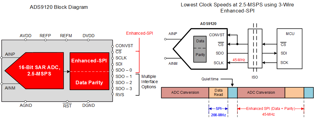
ADS9120を使用すると、アナログ性能の向上とともに、TIの拡張SPI機能を使用して高分解能のデータ転送を維持できます。ADS9120は、拡張SPIにより低いクロック速度で高いスループットを達成できるため、基板のレイアウトを簡素化し、システムのコストを低減できます。
また、拡張SPIによりデータのホスト・クロックインが簡素化されるため、このデバイスはFPGAやDSPに関係するアプリケーションに理想的です。ADS9120は、標準SPIインターフェイスと互換性があります。ADS9120には内部的なデータ・パリティ機能があり、ADCデータ出力にパリティを追加できます。パリティ・ビットを使用してホストでADCデータを検証することにより、システムの信頼性が向上します。
このデバイスはJESD8-7A準拠のI/Oをサポートし、拡張産業用温度範囲で動作し、省スペースの4mm×4mmのVQFNパッケージで供給されます。
フル・スループットでのSPIインターフェイス・クロック(1)
| 型番 | 3線式SPI | 3線式拡張SPI |
|---|---|---|
| ADS9120 | 200MHz | 45MHz |
- 拡張SPIのすべての機能については、「Interface Module」セクションを参照してください。
ADS9120による簡単なシステム設計
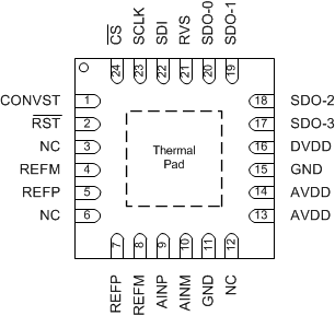
5 Pin Configuration and Functions
RGE Package
24-Pin VQFN
Top View
Pin Functions
| PIN | FUNCTION | DESCRIPTION | |
|---|---|---|---|
| NAME | NO. | ||
| AINM | 10 | Analog input | Negative analog input |
| AINP | 9 | Analog input | Positive analog input |
| AVDD | 13, 14 | Power supply | Analog power supply for the device |
| CONVST | 1 | Digital input | Conversion start input pin for the device. A CONVST rising edge brings the device from ACQ state to CNV state. |
| CS | 24 | Digital input | Chip-select input pin for the device; active low. The device takes control of the data bus when CS is low. The SDO-x pins go to tri-state when CS is high. |
| DVDD | 16 | Power supply | Interface supply |
| GND | 11, 15 | Power supply | Ground |
| NC | 3, 6, 12 | No connection | These pins must be left floating with no external connection |
| REFM | 4, 8 | Analog input | Reference ground potential |
| REFP | 5, 7 | Analog input | Reference voltage input |
| RST | 2 | Digital input | Asynchronous reset input pin for the device. A low pulse on the RST pin resets the device and all register bits return to a default state. |
| RVS | 21 | Digital output | Multi-function output pin for the device. With CS held high, RVS reflects the status of the internal ADCST signal. With CS low, the status of RVS depends on the output protocol selection. |
| SCLK | 23 | Digital input | Clock input pin for the serial interface. All system-synchronous data transfer protocols are timed with respect to the SCLK signal. |
| SDI | 22 | Digital input | Serial data input pin for the device. This pin is used to feed the data or command into the device. |
| SDO-0 | 20 | Digital output | Serial communication: data output 0 |
| SDO-1 | 19 | Digital output | Serial communication: data output 1 |
| SDO-2 | 18 | Digital output | Serial communication: data output 2 |
| SDO-3 | 17 | Digital output | Serial communication: data output 3 |
| Thermal pad | Supply | Exposed thermal pad; connecting this pin to GND is recommended | |
6 Specifications
6.1 Absolute Maximum Ratings
over operating free-air temperature range (unless otherwise noted)(1)| MIN | MAX | UNIT | |
|---|---|---|---|
| AVDD to GND | –0.3 | 2.1 | V |
| DVDD to GND | –0.3 | 2.1 | V |
| REFP to REFM | –0.3 | 5.5 | V |
| REFM to GND | –0.1 | 0.1 | V |
| Analog (AINP, AINM) to GND | –0.3 | REFP + 0.3 | V |
| Digital input (RST, CONVST, CS, SCLK, SDI) to GND | –0.3 | DVDD + 0.3 | V |
| Digital output (RVS, SDO-0, SDO-1, SDO-2, SDO-3) to GND | –0.3 | DVDD + 0.3 | V |
| Operating temperature, TA | –40 | 85 | °C |
| Storage temperature, Tstg | –65 | 150 | °C |
(1) Stresses beyond those listed under Absolute Maximum Ratings may cause permanent damage to the device. These are stress ratings only, which do not imply functional operation of the device at these or any other conditions beyond those indicated under Recommended Operating Conditions. Exposure to absolute-maximum-rated conditions for extended periods may affect device reliability.
6.2 ESD Ratings
| VALUE | UNIT | |||
|---|---|---|---|---|
| V(ESD) | Electrostatic discharge | Human-body model (HBM), per ANSI/ESDA/JEDEC JS-001(1) | ±2000 | V |
| Charged-device model (CDM), per JEDEC specification JESD22-C101(2) | ±500 | |||
(1) JEDEC document JEP155 states that 500-V HBM allows safe manufacturing with a standard ESD control process.
(2) JEDEC document JEP157 states that 250-V CDM allows safe manufacturing with a standard ESD control process.
6.3 Recommended Operating Conditions
over operating free-air temperature range (unless otherwise noted)| MIN | NOM | MAX | UNIT | ||
|---|---|---|---|---|---|
| AVDD | Analog supply voltage | 1.8 | V | ||
| DVDD | Digital supply voltage | 1.8 | V | ||
| REFP | Positive reference | 5 | V | ||
6.4 Thermal Information
| THERMAL METRIC(1) | ADS9120 | UNITS | |
|---|---|---|---|
| RGE (VQFN) | |||
| 24 PINS | |||
| RθJA | Junction-to-ambient thermal resistance | 31.9 | °C/W |
| RθJC(top) | Junction-to-case (top) thermal resistance | 29.9 | °C/W |
| RθJB | Junction-to-board thermal resistance | 8.9 | °C/W |
| ψJT | Junction-to-top characterization parameter | 0.3 | °C/W |
| ψJB | Junction-to-board characterization parameter | 8.9 | °C/W |
| RθJC(bot) | Junction-to-case (bottom) thermal resistance | 2.0 | °C/W |
(1) For more information about traditional and new thermal metrics, see the Semiconductor and IC Package Thermal Metrics application report.
6.5 Electrical Characteristics
All specifications are for AVDD = 1.8 V, DVDD = 1.8 V, VREF = 5 V, and fDATA = 2.5 MSPS, unless otherwise noted.All minimum and maximum specifications are for TA = –40°C to +85°C, unless otherwise noted.
All typical values are at TA = 25°C.
| PARAMETER | TEST CONDITIONS | MIN | TYP | MAX | UNIT | |
|---|---|---|---|---|---|---|
| ANALOG INPUT | ||||||
| FSR | Full-scale input range (AINP – AINM)(1) |
–VREF | VREF | V | ||
| VIN | Absolute input voltage (AINP and AINM to REFGND) |
–0.1 | VREF + 0.1 | V | ||
| VCM | Common-mode voltage range (AINP + AINM) / 2 |
(VREF / 2) – 0.1 | VREF / 2 | (VREF / 2) + 0.1 | V | |
| CIN | Input capacitance | In sample mode | 60 | pF | ||
| In hold mode | 4 | |||||
| IIL | Input leakage current | ±1 | µA | |||
| VOLTAGE REFERENCE INPUT | ||||||
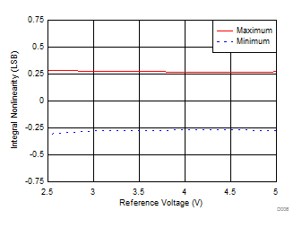
| VREF | Reference input voltage range | 2.5 | 5 | V | ||
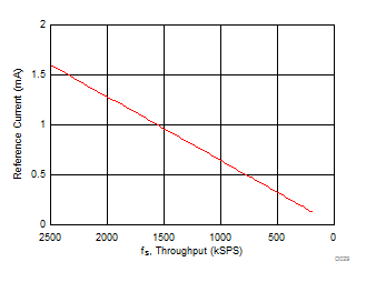
| IREF | Reference input current | Average current, VREF = 5 V, 2-kHz, full-scale input, throughput = 2.5 MSPS |
1.3 | mA | ||
| DC ACCURACY | ||||||
| Resolution | 16 | Bits | ||||
| NMC | No missing codes | 16 | Bits | |||
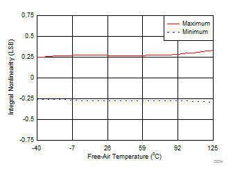
| INL | Integral nonlinearity | TA = –40°C to +85°C | –0.6 | ±0.25(2) | 0.6 | LSB(3) |
| TA = –40°C to +125°C | –0.7 | ±0.25(2) | 0.7 | |||
| DNL | Differential nonlinearity | TA = –40°C to +85°C | –0.6 | ±0.25(2) | 0.6 | LSB |
| TA = –40°C to +125°C | –0.7 | ±0.25 | 0.7 | |||
| E(IO) | Input offset error | –1 | ±0.025(2) | 1 | mV | |
| dVOS/dT | Input offset thermal drift | 1 | μV/°C | |||
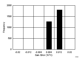
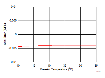
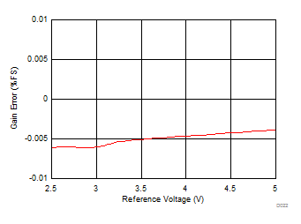
| GE | Gain error | –0.02 | ±0.01(2) | 0.02 | %FS | |
| GE/dT | Gain error thermal drift | 0.25 | ppm/°C | |||
| Transition noise | 0.35 | LSB | ||||
| CMRR | Common-mode rejection ratio | At dc to 20 kHz | 80 | dB | ||
| AC ACCURACY(4) | ||||||
| SINAD | Signal-to-noise + distortion | fIN = 2 kHz | 94.4 | 96 | dB | |
| fIN = 100 kHz | 95 | |||||
| fIN = 500 kHz | 83.9 | |||||
| SNR | Signal-to-noise ratio | fIN = 2 kHz | 94.5 | 96 | dB | |
| fIN = 100 kHz | 95.9 | |||||
| fIN = 500 kHz | 84 | |||||
| THD | Total harmonic distortion(5) | fIN = 2 kHz | –118 | dB | ||
| fIN = 100 kHz | –102 | |||||
| fIN = 500 kHz | –101 | |||||
| SFDR | Spurious-free dynamic range | fIN = 2 kHz | 120 | dB | ||
| fIN = 100 kHz | 108 | |||||
| fIN = 500 kHz | 106 | |||||
| DIGITAL INPUTS(6) | ||||||
| VIH | High-level input voltage | 0.65 DVDD | DVDD + 0.3 | V | ||
| VIL | Low-level input voltage | –0.3 | 0.35 DVDD | V | ||
| DIGITAL OUTPUTS(6) | ||||||
| VOH | High-level output voltage | IOH = 2-mA source | DVDD – 0.45 | V | ||
| VOL | Low-level output voltage | IOH = 2-mA sink | 0.45 | V | ||
| POWER SUPPLY | ||||||
| AVDD | Analog supply voltage | 1.65 | 1.8 | 1.95 | V | |
| DVDD | Digital supply voltage | 1.65 | 1.8 | 1.95 | V | |
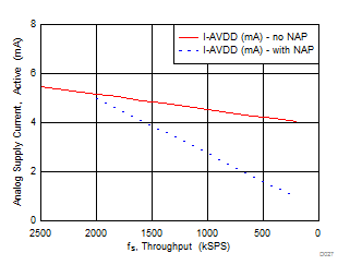
| IDD | AVDD supply current (AVDD = 1.8 V) |
Active, 2.5-MSPS throughput, TA = –40°C to +85°C |
5 | 6.5 | mA | |
| Active, 2.5-MSPS throughput, TA = –40°C to +125°C |
5 | 6.75 | ||||
| Static, ACQ state | 3.7 | mA | ||||
| Low-power, NAP mode | 500 | µA | ||||
| Power-down, PD state | 1 | |||||
| PD | AVDD power dissipation (AVDD = 1.8 V) |
Active, 2.5-MSPS throughput, TA = –40°C to +85°C |
9 | 11.7 | mW | |
| Active, 2.5-MSPS throughput, TA = –40°C to +125°C |
9 | 12.15 | ||||
| Static, ACQ state | 6.6 | mW | ||||
| Low-power, NAP mode | 900 | µW | ||||
| Power-down, PD state | 1.8 | |||||
| TEMPERATURE RANGE | ||||||
| TA | Operating free-air temperature | –40 | 125 | °C | ||
(1) Ideal input span, does not include gain or offset errors.
(2) See Figure 9, Figure 10, Figure 25, and Figure 26 for statistical distribution data for INL, DNL, offset, and gain error parameters.
(3) LSB = least-significant bit. 1 LSB at 18 bits is approximately 3.8 ppm.
(4) All specifications expressed in decibels (dB) refer to the full-scale input (FSR) and are tested with an input signal 0.1 dB below full-scale, unless otherwise specified.
(5) Calculated on the first nine harmonics of the input frequency.
(6) As per the JESD8-7A standard. Specified by design; not production tested.
6.6 Timing Requirements: Conversion Cycle
All specifications are for AVDD = 1.8 V, DVDD = 1.8 V, VREF = 5 V, and fDATA = 2.5 MSPS, unless otherwise noted.All minimum and maximum specifications are for TA = –40°C to +85°C. All typical values are at TA = 25°C. See Figure 1.
| MIN | TYP | MAX | UNIT | ||
|---|---|---|---|---|---|
| TIMING REQUIREMENTS | |||||
| fcycle | Sampling frequency | 2.5 | MHz | ||
| tcycle | ADC cycle time period | 400 | ns | ||
| twh_CONVST | Pulse duration: CONVST high | 30 | ns | ||
| twl_CONVST | Pulse duration: CONVST low | 30 | ns | ||
| tacq | Acquisition time | 100 | ns | ||
| tqt_acq | Quiet acquisition time(1) | 25 | ns | ||
| td_cnvcap | Quiet aperture time(1) | 10 | ns | ||
| TIMING SPECIFICATIONS | |||||
| tconv | Conversion time | 270 | 290 | ns | |
(1) See Figure 47.
6.7 Timing Requirements: Asynchronous Reset, NAP, and PD
All specifications are for AVDD = 1.8 V, DVDD = 1.8 V, VREF = 5 V, and fDATA = 2.5 MSPS, unless otherwise noted.All minimum and maximum specifications are for TA = –40°C to +85°C. All typical values are at TA = 25°C. See Figure 2 and Figure 3.
| MIN | TYP | MAX | UNIT | ||
|---|---|---|---|---|---|
| TIMING REQUIREMENTS | |||||
| twl_RST | Pulse duration: RST low | 100 | ns | ||
| TIMING SPECIFICATIONS | |||||
| td_rst | Delay time: RST rising to RVS rising | 1250 | µs | ||
| tnap_wkup | Wake-up time: NAP mode | 300 | ns | ||
| tPWRUP | Power-up time: PD mode | 250 | µs | ||
6.8 Timing Requirements: SPI-Compatible Serial Interface
All specifications are for AVDD = 1.8 V, DVDD = 1.8 V, VREF = 5 V, and fDATA = 2.5 MSPS, unless otherwise noted.All minimum and maximum specifications are for TA = –40°C to +85°C. All typical values are at TA = 25°C. See Figure 4.
| MIN | TYP | MAX | UNIT | |||
|---|---|---|---|---|---|---|
| TIMING REQUIREMENTS | ||||||
| fCLK | Serial clock frequency | 75 | MHz | |||
| tCLK | Serial clock time period | 13.33 | ns | |||
| tph_CK | SCLK high time | 0.45 | 0.55 | tCLK | ||
| tpl_CK | SCLK low time | 0.45 | 0.55 | tCLK | ||
| tsu_CSCK | Setup time: CS falling to the first SCLK capture edge | 5 | ns | |||
| tsu_CKDI | Setup time: SDI data valid to the SCLK capture edge | 1.2 | ns | |||
| tht_CKDI | Hold time: SCLK capture edge to (previous) data valid on SDI | 0.65 | ns | |||
| tht_CKCS | Delay time: last SCLK falling to CS rising | 5 | ns | |||
| TIMING SPECIFICATIONS | ||||||
| tden_CSDO | Delay time: CS falling to data enable | 4.5 | ns | |||
| tdz_CSDO | Delay time: CS rising to SDO going to 3-state | 10 | ns | |||
| td_CKDO | Delay time: SCLK launch edge to (next) data valid on SDO | 6.5 | ns | |||
| td_CSRDY_f | Delay time: CS falling to RVS falling | 5 | ns | |||
| td_CSRDY_r | Delay time: CS rising to RVS rising |
After NOP operation | 10 | ns | ||
| After WR or RD operation | 70 | |||||
6.9 Timing Requirements: Source-Synchronous Serial Interface (External Clock)
All specifications are for AVDD = 1.8 V, DVDD = 1.8 V, VREF = 5 V, and fDATA = 2.5 MSPS, unless otherwise noted.All minimum and maximum specifications are for TA = –40°C to +85°C. All typical values are at TA = 25°C. See Figure 5.
| MIN | TYP | MAX | UNIT | ||
|---|---|---|---|---|---|
| TIMING REQUIREMENTS | |||||
| fCLK | Serial clock frequency | 100 | MHz | ||
| tCLK | Serial clock time period | 10 | ns | ||
| TIMING SPECIFICATIONS(1) | |||||
| td_CKSTR_r | Delay time: SCLK launch edge to RVS rising | 8.5 | ns | ||
| td_CKSTR_f | Delay time: SCLK launch edge to RVS falling | 8.5 | ns | ||
| toff_STRDO_f | Time offset: RVS rising to (next) data valid on SDO | –0.5 | 0.5 | ns | |
| toff_STRDO_r | Time offset: RVS falling to (next) data valid on SDO | –0.5 | 0.5 | ns | |
(1) Other parameters are the same as the Timing Requirements: SPI-Compatible Serial Interface table.
6.10 Timing Requirements: Source-Synchronous Serial Interface (Internal Clock)
All specifications are for AVDD = 1.8 V, DVDD = 1.8 V, VREF = 5 V, and fDATA = 2.5 MSPS, unless otherwise noted.All minimum and maximum specifications are for TA = –40°C to +85°C. All typical values are at TA = 25°C. See Figure 6.
| MIN | TYP | MAX | UNIT | |||
|---|---|---|---|---|---|---|
| TIMING SPECIFICATIONS(1) | ||||||
| td_CSSTR | Delay time: CS falling to RVS rising | 12 | 40 | ns | ||
| toff_STRDO_f | Time offset: RVS rising to (next) data valid on SDO | –0.5 | 0.5 | ns | ||
| toff_STRDO_r | Time offset: RVS falling to (next) data valid on SDO | –0.5 | 0.5 | ns | ||
| tSTR | Strobe output time period | INTCLK option | 9.9 | 11.1 | ns | |
| INTCLK / 2 option | 19.8 | 22.2 | ||||
| INTCLK / 4 option | 39.6 | 44.4 | ||||
| tph_STR | Strobe output high time | 0.45 | 0.55 | tSTR | ||
| tpl_STR | Strobe output low time | 0.45 | 0.55 | tSTR | ||
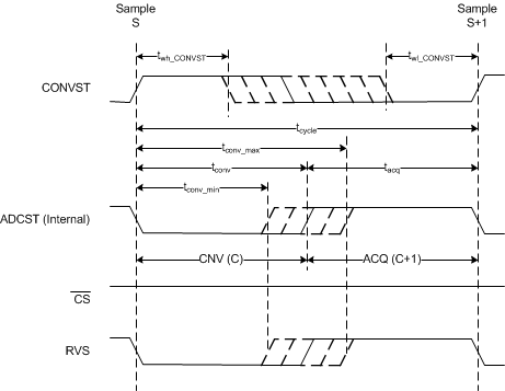 Figure 1. Conversion Cycle Timing Diagram
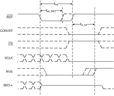 Figure 2. Asynchronous Reset Timing Diagram
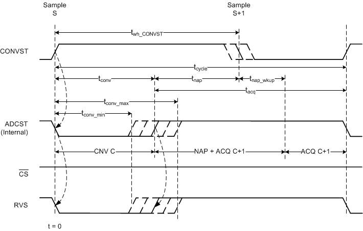 Figure 3. NAP Mode Timing Diagram
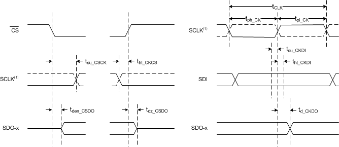
1. The SCLK polarity, launch edge, and capture edge depend on the SPI protocol selected.
Figure 4. SPI-Compatible Serial Interface Timing Diagram
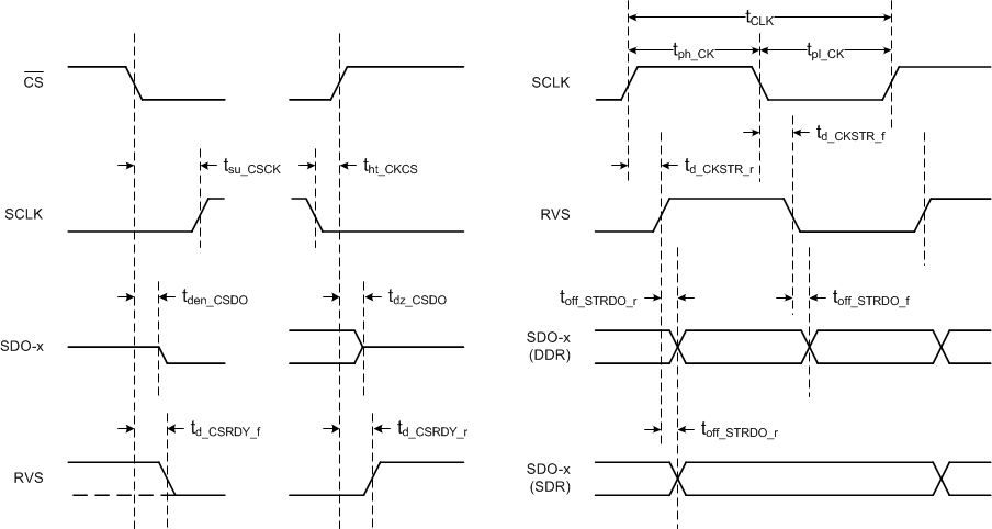 Figure 5. Source-Synchronous Serial Interface Timing Diagram (External Clock)
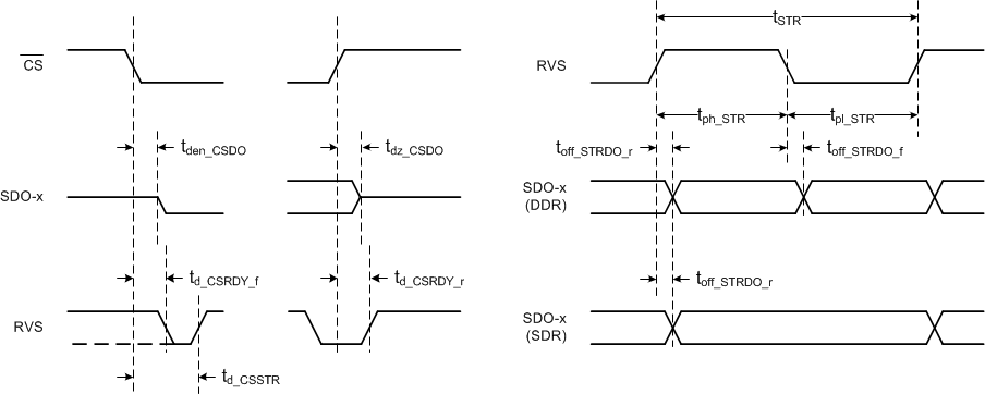 Figure 6. Source-Synchronous Serial Interface Timing Diagram (Internal Clock)
6.11 Typical Characteristics
at TA = 25°C, AVDD = 1.8 V, DVDD = 1.8 V, VREF = 5 V, and fSAMPLE = 2.5 MSPS (unless otherwise noted)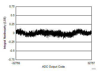
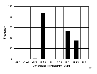
| Typical INL = ±0.25 LSB |
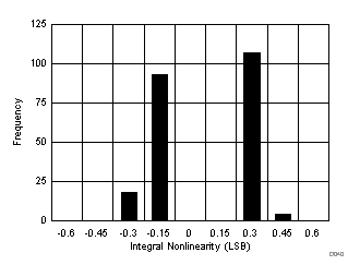
| 120 devices |
| VREF = 5 V |
| TA = 25°C |
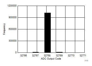
| Standard deviation = 0.35 LSB |
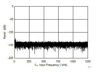
| fIN = 2 kHz, SNR = 96 dB, THD = –118 dB |
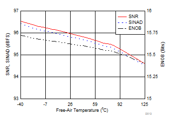
| fIN = 2 kHz, VREF = 5 V |
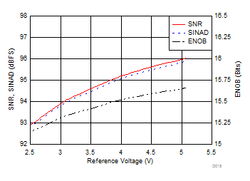
| fIN = 2 kHz, TA = 25°C |
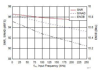
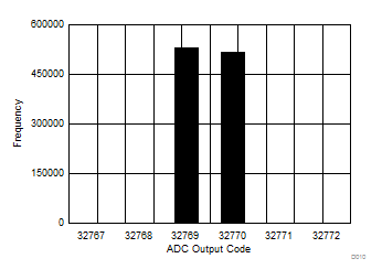
| VREF = 5 V, TA = 25°C |
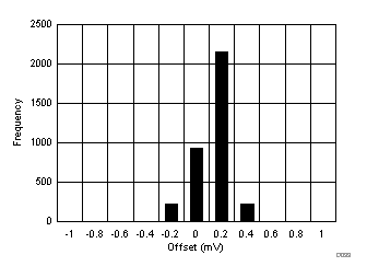
| 3500 devices |
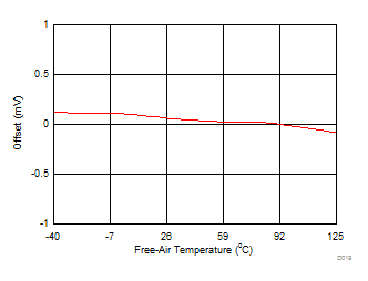
| VREF = 5 V |
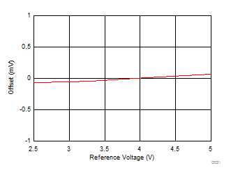
| TA = 25°C |
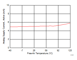
| 2.5 MSPS |
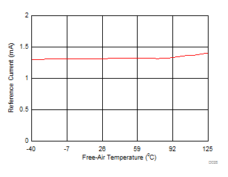
| 2.5 MSPS |
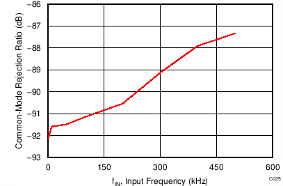
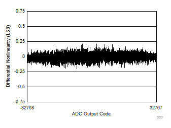
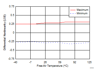
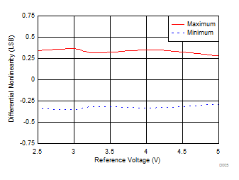
| Typical DNL = ±0.25 LSB |
| 120 devices |
| VREF = 5 V |
| TA = 25°C |
| Standard deviation = 0.35 LSB |
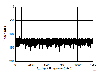
| fIN = 100 kHz, SNR = 95.9 dB, THD = –102 dB |
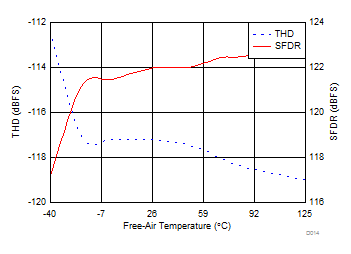
| fIN = 2 kHz, VREF = 5 V |
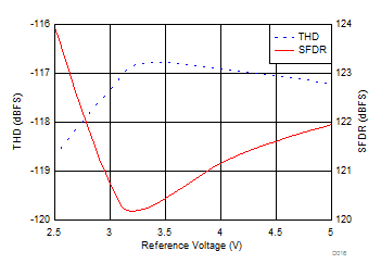
| fIN = 2 kHz, TA = 25°C |
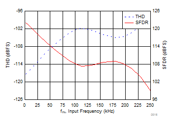
| VREF = 5 V, TA = 25°C |
| 3500 devices |
| VREF = 5 V |
| TA = 25°C |
| TA = 25°C |
| TA = 25°C |