JAJSHJ6B December 2011 – June 2019 AFE030
PRODUCTION DATA.
- 1 特長
- 2 アプリケーション
- 3 概要
- 4 改訂履歴
- 5 概要 (続き)
- 6 Pin Configuration and Functions
-
7 Specifications
- 7.1 Absolute Maximum Ratings
- 7.2 ESD Ratings
- 7.3 Thermal Information
- 7.4 Electrical Characteristics: Transmitter (Tx), Tx_DAC
- 7.5 Electrical Characteristics: Transmitter (Tx), Tx_PGA
- 7.6 Electrical Characteristics: Transmitter (Tx), Tx_FILTER
- 7.7 Electrical Characteristics: Power Amplifier (PA)
- 7.8 Electrical Characteristics: Receiver (Rx), Rx PGA1
- 7.9 Electrical Characteristics: Receiver (Rx), Rx Filter
- 7.10 Electrical Characteristics: Receiver (Rx), Rx PGA2
- 7.11 Electrical Characteristics: Digital
- 7.12 Electrical Characteristics: Two-Wire Interface
- 7.13 Electrical Characteristics: Zero-Crossing Detector
- 7.14 Electrical Characteristics: Internal Bias Generator
- 7.15 Electrical Characteristics: Power Supply
- 7.16 Typical Characteristics
- 8 Parameter Measurement Information
- 9 Detailed Description
- 10Application and Implementation
- 11デバイスおよびドキュメントのサポート
パッケージ・オプション
メカニカル・データ(パッケージ|ピン)
- RGZ|48
サーマルパッド・メカニカル・データ
- RGZ|48
発注情報
10.4 Circuit Protection
Powerline communications are often located in operating environments that are harsh for electrical components connected to the ac line. Noise or surges from electrical anomalies such as lightning, capacitor bank switching, inductive switching, or other grid fault conditions can damage high-performance integrated circuits if they are not properly protected. The AFE030 can survive even the harshest conditions if several recommendations are followed.
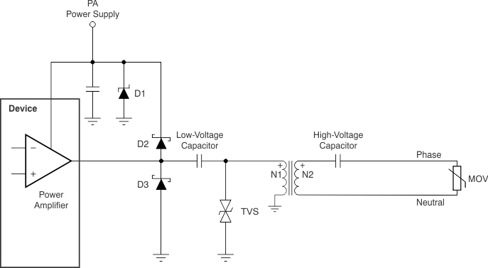
First, dissipate as much of the electrical disturbance before it reaches the AFE030 with a multi-layer approach using metal-oxide varistors (MOVs), transient voltage suppression diodes (TVSs), Schottky diodes, and a Zener diode. Figure 50 shows the recommended strategy for transient overvoltage protection.
 Figure 50. Transient Overvoltage Protection for AFE030
 Note that the high-voltage coupling capacitor must be able to withstand pulses up to the clamping protection provided by the MOV. A metalized polypropylene capacitor, such as the 474MKP275KA from Illinois Capacitor, Inc., is rated for 50 Hz to 60 Hz, 250 VAC to 310 VAC, and can withstand 24 impulses of 2.5 kV.
Table 20 lists several recommended transient protection components.
Table 20. Recommended Transient Protection Devices
| 120 VAC, 60 Hz | |||
|---|---|---|---|
| COMPONENT | DESCRIPTION | MANUFACTURER | MFR PART NO (OR EQUIVALENT) |
| D1 | Zener diode | Diodes, Inc. | 1SMB59xxB(1) |
| D2, D3 | Schottky diode | Diodes, Inc. | 1N5819HW |
| TVS | Transient voltage suppressor | Diodec Semiconductor | P6SMBJxxC(2) |
| MOV | Varistor | LittleFuse | TMOV20RP140E |
| HV Cap | High-voltage capacitor | Illinois Capacitor, Inc | 474MKP275KA(3) |
| 240 VAC, 50 Hz | |||
| COMPONENT | DESCRIPTION | MANUFACTURER | MFR PART NO (OR EQUIVALENT) |
| D1 | Zener diode | Diodes, Inc. | 1SMB59xxB(1) |
| D2, D3 | Schottky diode | Diodes, Inc. | 1N5819HW |
| TVS | Transient voltage suppressor | Diodec Semiconductor | P6SMBJxxC(2) |
| MOV | Varistor | LittleFuse | TMOV20RP300E |
| HV Cap | High-voltage capacitor | Illinois Capacitor, Inc | 474MKP275KA(3) |