SLUS618I August 2004 – December 2014
UNLESS OTHERWISE NOTED, this document contains PRODUCTION DATA.
- 1 Features
- 2 Applications
- 3 Description
- 4 Power Flow Diagram
- 5 Revision History
- 6 Description (continued)
- 7 Device Options
- 8 Pin Configuration and Functions
- 9 Specifications
-
10Detailed Description
- 10.1 Overview
- 10.2 Functional Block Diagram
- 10.3
Feature Description
- 10.3.1 bq24038 Differences
- 10.3.2 Power-Path Management
- 10.3.3 Charge Status Outputs
- 10.3.4 ACPG, USBPG Outputs (Power Good), bq24030/31/32A/35
- 10.3.5 PG Output (Power Good), bq24038
- 10.3.6 CE Input (Chip Enable)
- 10.3.7 VBSEL Input (Battery Voltage Selection), bq24038
- 10.3.8 DPPM Used As A Charge Disable Function
- 10.3.9 Timer Fault Recovery
- 10.3.10 Short-Circuit Recovery
- 10.3.11 LDO Regulator
- 10.4 Device Functional Modes
- 11Application and Implementation
- 12Power Supply Recommendations
- 13Layout
- 14Device and Documentation Support
- 15Mechanical, Packaging, and Orderable Information
パッケージ・オプション
デバイスごとのパッケージ図は、PDF版データシートをご参照ください。
メカニカル・データ(パッケージ|ピン)
- RHL|20
サーマルパッド・メカニカル・データ
- RHL|20
発注情報
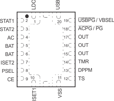
8 Pin Configuration and Functions
RHL Package
20 Pins
Top View
