SLUSDI4A October 2018 – April 2021 BQ25120F3A
PRODUCTION DATA
- 1 Features
- 2 Applications
- 3 Description
- 4 Revision History
- 5 Description (continued)
- 6 Device Comparison Table
- 7 Pin Configuration and Functions
- 8 Specifications
-
9 Detailed Description
- 9.1 Overview
- 9.2 Functional Block Diagram
- 9.3
Feature Description
- 9.3.1 Ship Mode
- 9.3.2 High Impedance Mode
- 9.3.3 Active Battery Only Connected
- 9.3.4 Voltage Based Battery Monitor
- 9.3.5 Sleep Mode
- 9.3.6 Input Voltage Based Dynamic Power Management (VIN(DPM))
- 9.3.7 Input Overvoltage Protection and Undervoltage Status Indication
- 9.3.8 Battery Charging Process and Charge Profile
- 9.3.9 Dynamic Power Path Management Mode
- 9.3.10 Battery Supplement Mode
- 9.3.11 Default Mode
- 9.3.12 Termination and Pre-Charge Current Programming by External Components (IPRETERM)
- 9.3.13 Input Current Limit Programming by External Components (ILIM)
- 9.3.14 Charge Current Programming by External Components (ISET)
- 9.3.15 Safety Timer and Watchdog Timer
- 9.3.16 External NTC Monitoring (TS)
- 9.3.17 Thermal Protection
- 9.3.18 Typical Application Power Dissipation
- 9.3.19 Status Indicators ( PG and INT)
- 9.3.20 Chip Disable ( CD)
- 9.3.21 Buck (PWM) Output
- 9.3.22 Load Switch / LDO Output and Control
- 9.3.23 Manual Reset Timer and Reset Output ( MR and RESET)
- 9.4 Device Functional Modes
- 9.5 Programming
- 9.6
Register Maps
- 9.6.1 Status and Ship Mode Control Register
- 9.6.2 Faults and Faults Mask Register
- 9.6.3 TS Control and Faults Masks Register
- 9.6.4 Fast Charge Control Register
- 9.6.5 Termination/Pre-Charge and I2C Address Register
- 9.6.6 Battery Voltage Control Register
- 9.6.7 SYS VOUT Control Register
- 9.6.8 Load Switch and LDO Control Register
- 9.6.9 Push-button Control Register
- 9.6.10 ILIM and Battery UVLO Control Register
- 9.6.11 Voltage Based Battery Monitor Register
- 9.6.12 VIN_DPM and Timers Register
- 10Application and Implementation
- 11Power Supply Recommendations
- 12Layout
- 13Device and Documentation Support
- 14Mechanical, Packaging, and Orderable Information
8.6 Timing Requirements
| MIN | TYP | MAX | UNIT | |||
|---|---|---|---|---|---|---|
| POWER-PATH MANAGEMENT AND INPUT CURRENT LIMIT | ||||||
| tDGL_SC | Deglitch Time, PMID or SW Short Circuit during Discharge Mode | 250 | µs | |||
| tREC_SC | Recovery time, OUT Short Circuit during Discharge Mode | 2 | s | |||
| BATTERY CHARGER | ||||||
| tDGL_SHORT | Deglitch time transition from ISET short to I(CHARGE) disable | Clear fault by disconnecting VIN | 1 | ms | ||
| BATTERY CHARGING TIMERS | ||||||
| tMAXCHG | Charge safety timer | Programmable range | 2 | 540 | min | |
| tPRECHG | Precharge safety timer | 0.1 x tMAXCHG | ||||
| SYS OUTPUT | ||||||
| tONMIN | Minimum ON time | VIN = 3.6 V, VOUT = 2 V, IOUT = 0 mA | 225 | ns | ||
| tOFFMIN | Minimum OFF time | VIN = 4.2 V | 50 | ns | ||
| tSTART_SW | SW start up time | VIN = 5 V, from write on EN_SW_OUT until output starts to rise | 5 | 25 | ms | |
| tSTART_SYS | SYS output time to start switching | From insertion of BAT > V(BUVLO) or VIN > V(UVLO) | 350 | µs | ||
| tSOFTSTART | Softstart time with reduced current limit | 400 | 1200 | µs | ||
| LS/LDO OUTPUT | ||||||
| tON_LDO | Turn ON time | 100-mA load | 500 | µs | ||
| tOFF_LDO | Turn OFF time | 100-mA load | 5 | µs | ||
| PUSHBUTTON TIMER | ||||||
| tWAKE1 | Push button timer wake 1 | Programmable Range for wake1 function | 0.08 | 1 | s | |
| tWAKE2 | Push button timer wake 2 | Programmable Range for wake2 function | 1 | 2 | s | |
| tRESET | Push button timer reset | Programmable Range for reset function | 5 | 15 | s | |
| tRESET_D | Reset pulse duration | 400 | ms | |||
| tDD | Detection delay (from MR, input to RESET) | For 0s condition | 6 | µs | ||
| BATTERY-PACK NTC MONITOR | ||||||
| tDGL(TS) | Deglitch time on TS change | Applies to V(HOT), V(WARM), V(COOL), and V(COLD) | 50 | ms | ||
| I2C INTERFACE | ||||||
| tWATCHDOG | I2C interface reset timer for host | 50 | s | |||
| tI2CRESET | I2C interface inactive reset timer | 700 | ms | |||
| tHIZ_ACTIVEBAT | Transition time required to enable the I2C interface from HiZ to Active BAT | 1 | ms | |||
| INPUT PIN | ||||||
| t/CD_DGL | Deglitch for CD | CD rising/falling | 100 | µs | ||
| tQUIET | Input quiet time for Ship Mode transition | 1 | ms | |||

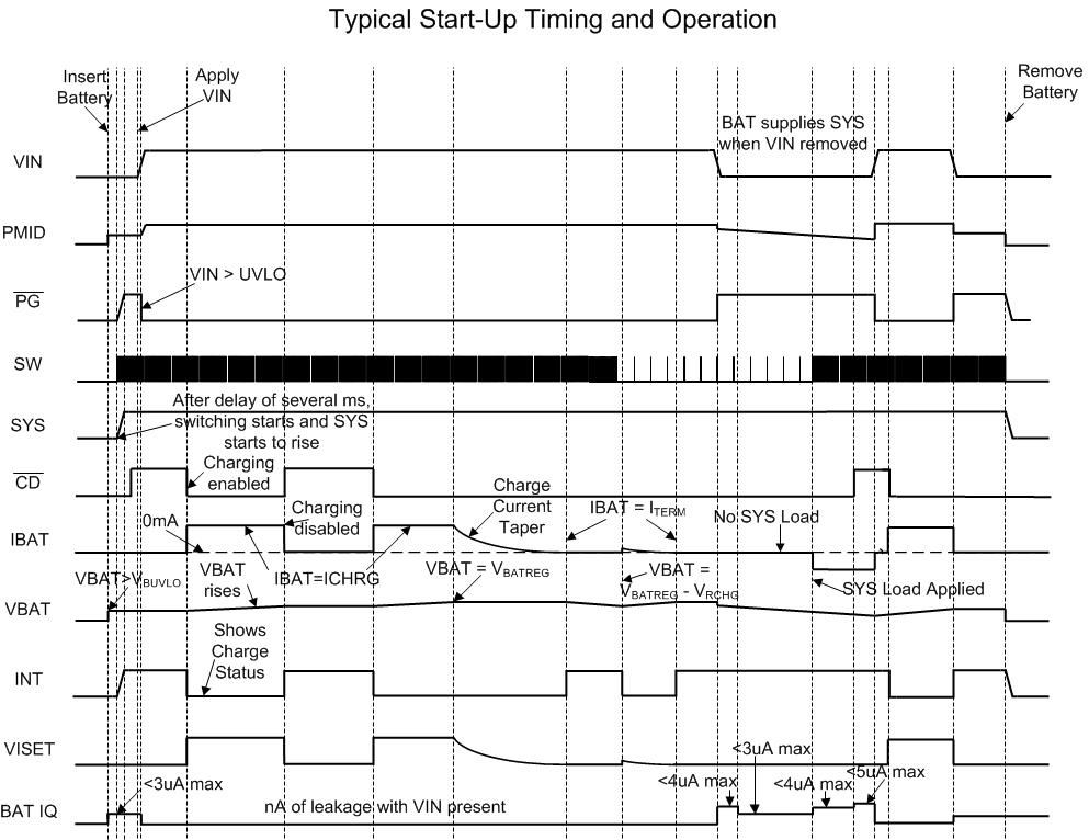
Conditions: PGB_MRS = 0,
TE = 1, SW_LDO = 1, VINDPM_ON = 0, PG and INT pulled up to SYS,
EN_INT = 1
Figure 8-1 Typical Start-Up
Timing and Operation
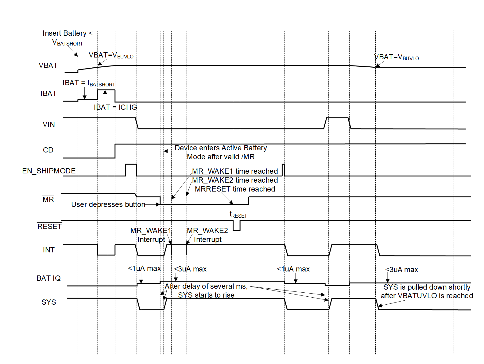
Conditions: SW_LDO = 1,
MRREC = 1, PG and INT pulled up to SYS, ISYS = 10 µA, EN_INT =
1
Figure 8-2 Battery Operation
and Sleep Mode