JAJSCJ2 October 2016
PRODUCTION DATA.
- 1 特長
- 2 アプリケーション
- 3 概要
- 4 改訂履歴
- 5 Pin Configuration and Functions
- 6 Specifications
- 7 Typical Characteristics
-
8 Detailed Description
- 8.1 Overview
- 8.2 Functional Block Diagram
- 8.3
Feature Description
- 8.3.1 Device Power Up
- 8.3.2 Battery Switch (Q1 + Q2)
- 8.3.3 Integrated 10-bit ADC for Monitoring
- 8.3.4 Linear Regulation Mode (LDO)
- 8.3.5
Protection Features
- 8.3.5.1 Reverse Current Protection (RCP)
- 8.3.5.2 Internal Thermal Shutdown
- 8.3.5.3 Input Overvoltage Protection
- 8.3.5.4 IBUS and VBUS Protection
- 8.3.5.5 IBAT and VBAT Protection
- 8.3.5.6 VOUT Protection
- 8.3.5.7 VDROP Protection
- 8.3.5.8 VBUS Temperature (TS_BUS_FLT) and Battery Temperature (TS_BAT_FLT)
- 8.3.6 I2C Serial Interface
- 8.4 Device Functional Modes
- 8.5
I2C Register Maps
- 8.5.1 I2C Register Summary Table
- 8.5.2 REG00 (DEVICE_INFO)
- 8.5.3 REG01 (EVENT_1_MASK)
- 8.5.4 REG02 (EVENT_2_MASK)
- 8.5.5 REG03 (EVENT_1)
- 8.5.6 REG04 (EVENT_2)
- 8.5.7 REG05 (EVENT_1_EN)
- 8.5.8 REG06 (CONTROL)
- 8.5.9 REG07 (ADC_CONTROL)
- 8.5.10 REG08 (ADC_EN)
- 8.5.11 REG09 (PROTECTION)
- 8.5.12 REG0A (VBUS_OVP)
- 8.5.13 REG0B (VOUT_REG)
- 8.5.14 REG0C (VDROP_OVP)
- 8.5.15 REG0D (VDROP_ALM)
- 8.5.16 REG0E (VBAT_REG)
- 8.5.17 REG0F (IBAT_REG)
- 8.5.18 REG10 (IBUS_REG)
- 8.5.19 REG11 (TS_BUS_FLT)
- 8.5.20 REG12 (TS_BAT_FLT)
- 8.5.21 REG 13 and REG 14 (VBUS_ADC)
- 8.5.22 REG15 and REG16 (IBUS_ADC)
- 8.5.23 REG17 and REG18 (VOUT_ADC)
- 8.5.24 REG19 and REG1A (VDROP_ADC)
- 8.5.25 REG1B and REG1C (VBAT_ADC)
- 8.5.26 REG1D and REG1E (IBAT_ADC)
- 8.5.27 REG1F and REG20 (TS_BUS_ADC)
- 8.5.28 REG21 and REG22 (TS_BAT_ADC)
- 8.5.29 REG 23 (TDIE_ADC)
- 8.5.30 REG 24 (EVENT_2_EN)
- 8.5.31 REG 25 (EVENT_3_MASK)
- 8.5.32 REG 26 (EVENT_3)
- 8.5.33 REG27 and REG28 (VUSB_ADC)
- 8.5.34 REG 29 (CONTROL_2)
- 8.5.35 REG 40 (DIE_TEMP_FLT)
- 9 Application and Implementation
- 10Power Supply Recommendations
- 11Layout
- 12デバイスおよびドキュメントのサポート
- 13メカニカル、パッケージ、および注文情報
11 Layout
11.1 Layout Guidelines
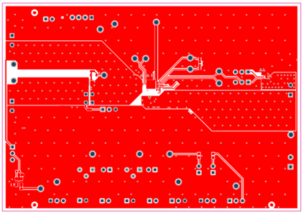
bq25872 supports up to 7-A charge current. It is very critical to maximize Cu trace of VBUS and VOUT. Following PCB layout guideline is recommended:
- Use Cu trace of at least 110 mil (2.794 mm) wide for VBUS and VOUT respectively. This allows current flow evenly through all 7 WCSP solder balls.
- Cu trace of VBUS and VOUT should run at least 150 mil (3.81 mm) straight (perpendicular to WCSP ball array) before making turns.
- Use as large as possible Cu pour for VBUS and VOUT trace elsewhere.
- Use as large as possible Cu pour for PGND.
- Place decoupling capacitors of VBUS and VOUT as close as possible to the device.
11.2 Layout Example
 Figure 63. bq25872 Layout Diagram (Top Layer)
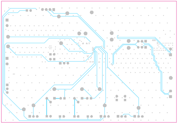
 Figure 64. bq25872 Layout Diagram (Mid Layer 2)
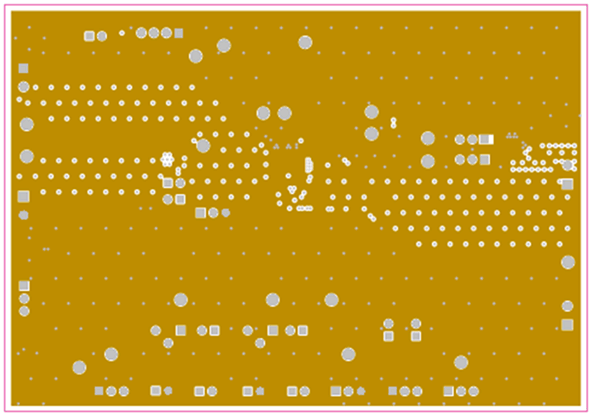
 Figure 65. bq25872 Layout Diagram (Mid Layer 1)
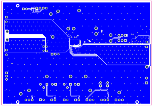
 Figure 66. bq25872 Layout Diagram (Bottom 1)