JAJSNB9C November   2012  – November 2021

PRODUCTION DATA  

  1. 特長
  2. アプリケーション
  3. 概要
  4. Revision History
  5. Device Comparison Table
  6. Pin Configuration and Functions
  7. Specifications
    1. 7.1  Absolute Maximum Ratings
    2. 7.2  ESD Ratings
    3. 7.3  Recommended Operating Conditions
    4. 7.4  Thermal Information
    5. 7.5  Electrical Characteristics: Supply Current
    6. 7.6  Digital Input and Output DC Characteristics
    7. 7.7  Power-on Reset
    8. 7.8  2.5-V LDO Regulator
    9. 7.9  Internal Clock Oscillators
    10. 7.10 ADC (Temperature and Cell Measurement) Characteristics
    11. 7.11 Integrating ADC (Coulomb Counter) Characteristics
    12. 7.12 Data Flash Memory Characteristics
    13. 7.13 I2C-Compatible Interface Communication Timing Requirements
    14. 7.14 Typical Characteristics
  8. Detailed Description
    1. 8.1 Overview
    2. 8.2 Functional Block Diagram
    3. 8.3 Feature Description
    4. 8.4 Device Functional Modes
      1. 8.4.1 Power Modes
        1. 8.4.1.1 BAT INSERT CHECK Mode
        2. 8.4.1.2 NORMAL Mode
        3. 8.4.1.3 SLEEP Mode
      2. 8.4.2 SLEEP+ Mode
      3. 8.4.3 HIBERNATE Mode
    5. 8.5 Programming
      1. 8.5.1 Standard Data Commands
      2. 8.5.2 Extended Data Commands
      3. 8.5.3 Communications
        1. 8.5.3.1 I2C Interface
        2. 8.5.3.2 I2C Time Out
        3. 8.5.3.3 I2C Command Waiting Time
        4. 8.5.3.4 I2C Clock Stretching
  9. Application and Implementation
    1. 9.1 Application Information
    2. 9.2 Typical Application
      1. 9.2.1 Design Requirements
      2. 9.2.2 Detailed Design Procedure
        1. 9.2.2.1 BAT Voltage Sense Input
        2. 9.2.2.2 SRP and SRN Current Sense Inputs
        3. 9.2.2.3 Sense Resistor Selection
        4. 9.2.2.4 TS Temperature Sense Input
        5. 9.2.2.5 Thermistor Selection
        6. 9.2.2.6 REGIN Power Supply Input Filtering
        7. 9.2.2.7 VCC LDO Output Filtering
      3. 9.2.3 Application Curves
  10. 10Power Supply Recommendations
    1. 10.1 Power Supply Decoupling
  11. 11Layout
    1. 11.1 Layout Guidelines
      1. 11.1.1 Sense Resistor Connections
      2. 11.1.2 Thermistor Connections
      3. 11.1.3 High-Current and Low-Current Path Separation
    2. 11.2 Layout Example
  12. 12Device and Documentation Support
    1. 12.1 Third-Party Products Disclaimer
    2. 12.2 Documentation Support
      1. 12.2.1 Related Documentation
    3. 12.3 Receiving Notification of Documentation Updates
    4. 12.4 サポート・リソース
    5. 12.5 Trademarks
    6. 12.6 Electrostatic Discharge Caution
    7. 12.7 Glossary
  13. 13Mechanical, Packaging, and Orderable Information

パッケージ・オプション

メカニカル・データ(パッケージ|ピン)
サーマルパッド・メカニカル・データ
発注情報

概要

テキサス・インスツルメンツ BQ27520-G4 システム側リチウムイオン・バッテリ残量計は、シングルセル・リチウムイオン・バッテリ・パックの残量計測を行うマイクロコントローラ・ペリフェラルで、最小限のシステム・マイクロコントローラ・ファームウェア開発で動作します。このバッテリ残量計はシステムのメイン・ボードに配置され、取り外し不可の組込みバッテリまたは着脱可能なバッテリ・パックを管理します。

特許取得の Impedance Track™ アルゴリズムを残量計測に使用し、残りのバッテリ容量 (mAh)、充電状態 (%)、残り動作時間 (最小値)、バッテリ電圧 (mV)、温度 (℃)、健全性状態 (%) などの情報を取得します。

バッテリ残量の計測に必要なのは、着脱可能なバッテリ・パックまたは内蔵バッテリ回路への PACK+ (P+)、PACK– (P–)、およびオプションのサーミスタ (T) 接続のみです。公称寸法 2610 × 1956µm、リード・ピッチ 0.5mm の 15 ボール NanoFree™ (DSBGA) パッケージを使用します。
このため、スペースに制約のあるアプリケーションに最適です。

製品情報
部品番号 パッケージ(1) 本体サイズ (公称)
BQ27520-G4 DSBGA (15) 2.610mm × 1.956mm
利用可能なすべてのパッケージについては、このデータシートの末尾にある注文情報を参照してください。
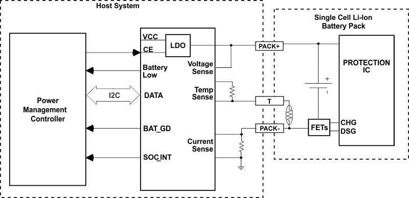
GUID-5898120A-DB2F-413D-80D2-F1636CE47D7C-low.gif代表的なアプリケーションの図