JAJSPG0 December 2022 BQ34Z100-R2
PRODUCTION DATA
- 1 特長
- 2 アプリケーション
- 3 概要
- 4 Revision History
- 5 Pin Configuration and Functions
-
6 Specifications
- 6.1 Absolute Maximum Ratings
- 6.2 ESD Ratings
- 6.3 Recommended Operating Conditions
- 6.4 Thermal Information
- 6.5 Electrical Characteristics: Power-On Reset
- 6.6 Electrical Characteristics: LDO Regulator
- 6.7 Electrical Characteristics: Internal Temperature Sensor Characteristics
- 6.8 Electrical Characteristics: Low-Frequency Oscillator
- 6.9 Electrical Characteristics: High-Frequency Oscillator
- 6.10 Electrical Characteristics: Integrating ADC (Coulomb Counter) Characteristics
- 6.11 Electrical Characteristics: ADC (Temperature and Cell Measurement) Characteristics
- 6.12 Electrical Characteristics: Data Flash Memory Characteristics
- 6.13 Timing Requirements: HDQ Communication
- 6.14 Timing Requirements: I2C-Compatible Interface
- 6.15 Typical Characteristics
- 7 Functional Block Diagram
-
8 Application and Implementation
- 8.1 Application Information
- 8.2
Typical Applications
- 8.2.1 Design Requirements
- 8.2.2
Detailed Design Procedure
- 8.2.2.1
Step-by-Step Design Procedure
- 8.2.2.1.1 STEP 1: Review and Modify the Data Flash Configuration Data.
- 8.2.2.1.2 STEP 2: Review and Modify the Data Flash Configuration Registers.
- 8.2.2.1.3 STEP 3: Design and Configure the Voltage Divider.
- 8.2.2.1.4 STEP 4: Determine the Sense Resistor Value.
- 8.2.2.1.5 STEP 5: Review and Modify the Data Flash Gas Gauging Configuration, Data, and State.
- 8.2.2.1.6 STEP 6: Determine and Program the Chemical ID.
- 8.2.2.1.7 STEP 7: Calibrate.
- 8.2.2.1.8 STEP 8: Run an Optimization Cycle.
- 8.2.2.1
Step-by-Step Design Procedure
- 9 Power Supply Recommendations
- 10Layout
- 11Device and Documentation Support
- 12Mechanical, Packaging, and Orderable Information
3 概要
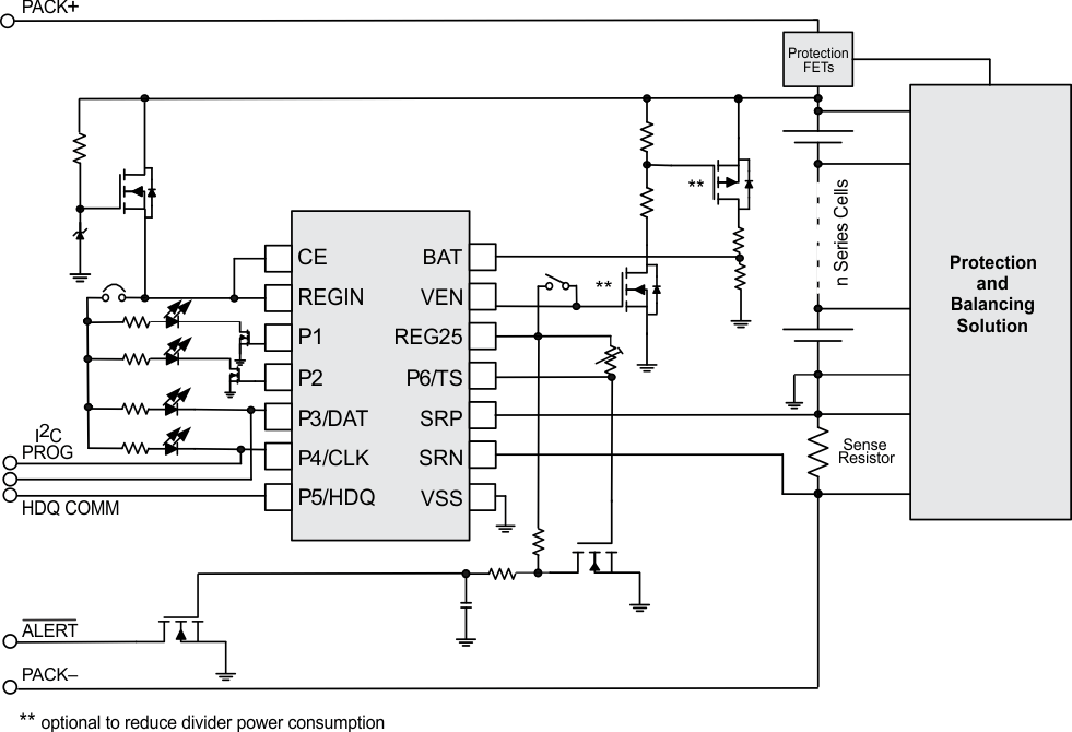
BQ34Z100-R2 デバイスは、リチウムイオン、PbA、NiMH、NiCd バッテリ向けの Impedance Track™ 残量計であり、バッテリの直列セル構成と無関係に動作します。システムの消費電力を低減するように自動的に制御される外部電圧変換回路を使って、3V~16.7KV のバッテリを簡単にサポートできます。
BQ34Z100-R2 デバイスは、I2C ペリフェラル、HDQ ペリフェラル、1 つまたは 4 つの直接 LED、ALERT 出力ピンを含む複数のインターフェイスの選択肢を備えています。また、BQ34Z100-R2 は、5 つ以上の LED のための外部ポート・エクスパンダもサポートしています。
製品情報
| 部品番号(1) | パッケージ | 本体サイズ (公称) |
|---|---|---|
| BQ34Z100-R2 | TSSOP (14) | 5.00mm × 4.40mm |
(1) 利用可能なパッケージについては、このデータシートの末尾にある注文情報を参照してください。
 簡略回路図
簡略回路図