JAJSCB2K April 2020 – July 2020 BQ77904 , BQ77905
PRODUCTION DATA
- 1 特長
- 2 アプリケーション
- 3 概要
- 4 Revision History
- 5 Device Comparison
- 6 Pin Configuration and Functions
- 7 Specifications
-
8 Detailed Description
- 8.1 Overview
- 8.2 Functional Block Diagram
- 8.3
Feature Description
- 8.3.1 Protection Summary
- 8.3.2
Fault Operation
- 8.3.2.1 Operation in OV
- 8.3.2.2 Operation in UV
- 8.3.2.3 Operation in OW
- 8.3.2.4 Operation in OCD1
- 8.3.2.5 Operation in OCD2
- 8.3.2.6 Operation in SCD
- 8.3.2.7 Overcurrent Recovery Timer
- 8.3.2.8 Load Removal Detection
- 8.3.2.9 Load Removal Detection in UV
- 8.3.2.10 Operation in OTC
- 8.3.2.11 Operation in OTD
- 8.3.2.12 Operation in UTC
- 8.3.2.13 Operation in UTD
- 8.3.3 Protection Response and Recovery Summary
- 8.3.4 Configuration CRC Check and Comparator Built-In-Self-Test
- 8.3.5 Fault Detection Method
- 8.3.6 State Comparator
- 8.3.7 DSG FET Driver Operation
- 8.3.8 CHG FET Driver Operation
- 8.3.9 External Override of CHG and DSG Drivers
- 8.3.10 Configuring 3-S, 4-S, or 5-S Mode
- 8.3.11 Stacking Implementations
- 8.3.12 Zero-Volt Battery Charging Inhibition
- 8.4 Device Functional Modes
- 9 Application and Implementation
- 10Power Supply Recommendations
- 11Layout
- 12Device and Documentation Support
- 13Mechanical, Packaging, and Orderable Information
3 概要
BQ77904 および BQ77905 デバイスは、低消費電力のバッテリ・パック・プロテクタで、電圧、電流、温度すべての保護を実装しており、マイクロコントローラ (MCU) による制御を必要としません。スタック可能なインターフェイスによって、単純なスケーリングにより 3 直列から 20 直列まで、さらにそれ以上のバッテリ・セルを持つアプリケーションに対応できます。保護のスレッショルドおよび遅延は工場出荷時に設定され、各種の構成で利用できます。過熱と低温のスレッショルドは、放電 (OTD および UTD) と充電 (OTC および UTC) についてそれぞれ別々に設定されるため、柔軟に使用できます。
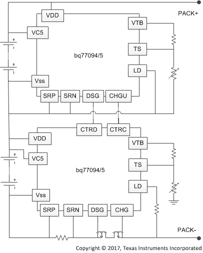
このデバイスは、内蔵の独立した CHG および DSG ローサイド NMOS FET ドライバを使用してパック保護を行います。これらは 2 つの制御ピンによってディセーブルできます。これらの制御ピンを使用して、単純かつ経済的な方法で、より多くの直列 (6 直列、またはそれ以上) セルの保護ソリューションを実現できます。このためには、上のデバイスの CHG および DSG 出力を、すぐ下のデバイスの制御ピンへカスケード接続します。部品数を減らすため、すべての保護フォルトは内部の遅延タイマを使用します。
製品情報
| 部品番号(1) | パッケージ | 本体サイズ (公称) |
|---|---|---|
| BQ77904 | TSSOP (20) | 6.50mm × 4.40mm |
| BQ77905 |
(1) 利用可能なすべてのパッケージについては、このデータシートの末尾にある注文情報を参照してください。
 概略回路図
概略回路図