JAJSMN3D August   1997  – July 2021 CD54HC10 , CD74HC10

PRODUCTION DATA  

  1. 特長
  2. アプリケーション
  3. 概要
  4. Revision History
  5. Pin Configuration and Functions
  6. Specifications
    1. 6.1 Absolute Maximum Ratings
    2. 6.2 ESD Ratings
    3. 6.3 Recommended Operating Conditions
    4. 6.4 Thermal Information
    5. 6.5 Electrical Characteristics
    6. 6.6 Switching Characteristics
    7. 6.7 Operating Characteristics
    8. 6.8 Typical Characteristics
  7. Parameter Measurement Information
  8. Detailed Description
    1. 8.1 Overview
    2. 8.2 Functional Block Diagram
    3. 8.3 Feature Description
      1. 8.3.1 Balanced CMOS Push-Pull Outputs
      2. 8.3.2 Standard CMOS Inputs
      3. 8.3.3 Clamp Diode Structure
    4. 8.4 Device Functional Modes
  9. Application and Implementation
    1. 9.1 Application Information
    2. 9.2 Typical Application
      1. 9.2.1 Design Requirements
        1. 9.2.1.1 Power Considerations
        2. 9.2.1.2 Input Considerations
        3. 9.2.1.3 Output Considerations
      2. 9.2.2 Detailed Design Procedure
      3. 9.2.3 Application Curves
        1.       Power Supply Recommendations
  10. 10Layout
    1. 10.1 Layout Guidelines
    2. 10.2 Layout Example
  11. 11Device and Documentation Support
    1. 11.1 Documentation Support
      1. 11.1.1 Related Documentation
    2. 11.2 ドキュメントの更新通知を受け取る方法
    3. 11.3 サポート・リソース
    4. 11.4 Trademarks
  12. 12静電気放電に関する注意事項
  13. 13用語集
  14. 14Mechanical, Packaging, and Orderable Information

パッケージ・オプション

デバイスごとのパッケージ図は、PDF版データシートをご参照ください。

メカニカル・データ(パッケージ|ピン)
  • J|14
サーマルパッド・メカニカル・データ
発注情報

概要

このデバイスには、3 つの独立した 3 入力 NAND ゲートが内蔵されています。各ゲートはブール関数 Y = A ● B ● C を正論理で実行します。

製品情報(1)
部品番号 パッケージ 本体サイズ (公称)
CD74HC10M SOIC (14) 8.70mm × 3.90mm
CD74HC10E PDIP (14) 19.30mm × 6.40mm
CD54HC10F CDIP (14) 21.30mm × 7.60mm
利用可能なパッケージについては、このデータシートの末尾にある注文情報を参照してください。
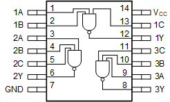
GUID-1FA671C7-5140-4CDC-8389-F94A478EEFE2-low.gif機能的なピン配置