SNAS621A JUNE 2013 – December 2014 DAC161S997
PRODUCTION DATA.
- 1 Features
- 2 Applications
- 3 Description
- 4 Simplified Schematic
- 5 Revision History
- 6 Pin Configuration and Functions
- 7 Specifications
- 8 Detailed Description
- 9 Application and Implementation
- 10Power Supply Recommendations
- 11Layout
- 12Device and Documentation Support
- 13Mechanical, Packaging, and Orderable Information
パッケージ・オプション
メカニカル・データ(パッケージ|ピン)
- RGH|16
サーマルパッド・メカニカル・データ
- RGH|16
発注情報
1 Features
- 16-Bit Resolution
- Very-Low Supply Current of 100 µA
- 5 ppmFS/°C Gain Error
- Pin-Programmable Power-Up Condition
- Loop-Error Detection and Reporting
- Programmable Output-Current Error Levels
- Simple HART Modulator Interfacing
- Highly Integrated Feature Set in Small Footprint WQFN-16 (4- × 4-mm, 0.5-mm Pitch)
2 Applications
3 Description
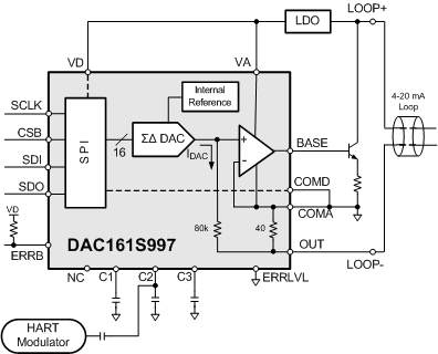
The DAC161S997 is a very low power 16-bit ΣΔ digital-to-analog converter (DAC) for transmitting an analog output current over an industry standard 4-20 mA current loop. The DAC161S997 has a simple 4-wire SPI for data transfer and configuration of the DAC functions. To reduce power and component count in compact loop-powered applications, the DAC161S997 contains an internal ultra-low power voltage reference and an internal oscillator. The low power consumption of the DAC161S997 results in additional current being available for the remaining portion of the system. The loop drive of the DAC161S997 interfaces to a Highway Addressable Remote Transducer (HART) modulator, allowing injection of FSK modulated digital data into the 4-20 mA current loop. This combination of specifications and features makes the DAC161S997 ideal for 2- and 4-wire industrial transmitters. The DAC161S997 is available in a 16-pin 4-mm × 4-mm WQFN package and is specified over the extended industrial temperature range of –40°C to +105°C.
Device Information(1)
| PART NUMBER | PACKAGE | BODY SIZE (NOM) |
|---|---|---|
| DAC161S997 | WQFN (16) | 4.00 mm x 4.00 mm |
- For all available packages, see the orderable addendum at the end of the datasheet.
4 Simplified Schematic
