-
DACx3004 12 ビットおよび 10 ビット、超低消費電力、クワッド電圧および電流出力スマート DAC、 I2C、PMBus™、SPI 自動検出機能付き
- 1 特長
- 2 アプリケーション
- 3 概要
- 4 Revision History
- 5 Pin Configuration and Functions
-
6 Specifications
- 6.1 Absolute Maximum Ratings
- 6.2 ESD Ratings
- 6.3 Recommended Operating Conditions
- 6.4 Thermal Information
- 6.5 Electrical Characteristics: Voltage Output
- 6.6 Electrical Characteristics: Current Output
- 6.7 Electrical Characteristics: Comparator Mode
- 6.8 Electrical Characteristics: General
- 6.9 Timing Requirements: I2C Standard Mode
- 6.10 Timing Requirements: I2C Fast Mode
- 6.11 Timing Requirements: I2C Fast Mode Plus
- 6.12 Timing Requirements: SPI Write Operation
- 6.13 Timing Requirements: SPI Read and Daisy Chain Operation (FSDO = 0)
- 6.14 Timing Requirements: SPI Read and Daisy Chain Operation (FSDO = 1)
- 6.15 Timing Requirements: GPIO
- 6.16 Timing Diagrams
- 6.17 Typical Characteristics: Voltage Output
- 6.18 Typical Characteristics: Current Output
- 6.19 Typical Characteristics: Comparator
- 6.20 Typical Characteristics: General
-
7 Detailed Description
- 7.1 Overview
- 7.2 Functional Block Diagram
- 7.3 Feature Description
- 7.4 Device Functional Modes
- 7.5 Programming
- 7.6
Register Map
- 7.6.1 NOP Register (address = 00h) [reset = 0000h]
- 7.6.2 DAC-X-MARGIN-HIGH Register (address = 01h, 07h, 0Dh, 13h) [reset = 0000h]
- 7.6.3 DAC-X-MARGIN-LOW Register (address = 02h, 08h, 0Eh, 14h) [reset = 0000h]
- 7.6.4 DAC-X-VOUT-CMP-CONFIG Register (address = 03h, 09h, 0Fh, 15h) [reset = 0000h]
- 7.6.5 DAC-X-IOUT-MISC-CONFIG Register (address = 04h, 0Ah, 10h, 16h) [reset = 0000h]
- 7.6.6 DAC-X-CMP-MODE-CONFIG Register (address = 05h, 0Bh, 11h, 17h) [reset = 0000h]
- 7.6.7 DAC-X-FUNC-CONFIG Register (address = 06h, 0Ch, 12h, 18h) [reset = 0000h]
- 7.6.8 DAC-X-DATA Register (address = 19h, 1Ah, 1Bh, 1Ch) [reset = 0000h]
- 7.6.9 COMMON-CONFIG Register (address = 1Fh) [reset = 0FFFh]
- 7.6.10 COMMON-TRIGGER Register (address = 20h) [reset = 0000h]
- 7.6.11 COMMON-DAC-TRIG Register (address = 21h) [reset = 0000h]
- 7.6.12 GENERAL-STATUS Register (address = 22h) [reset = 00h, DEVICE-ID, VERSION-ID]
- 7.6.13 CMP-STATUS Register (address = 23h) [reset = 0000h]
- 7.6.14 GPIO-CONFIG Register (address = 24h) [reset = 0000h]
- 7.6.15 DEVICE-MODE-CONFIG Register (address = 25h) [reset = 0000h]
- 7.6.16 INTERFACE-CONFIG Register (address = 26h) [reset = 0000h]
- 7.6.17 SRAM-CONFIG Register (address = 2Bh) [reset = 0000h]
- 7.6.18 SRAM-DATA Register (address = 2Ch) [reset = 0000h]
- 7.6.19 DAC-X-DATA-8BIT Register (address = 40h, 41h, 42h, 43h) [reset = 0000h]
- 7.6.20 BRDCAST-DATA Register (address = 50h) [reset = 0000h]
- 7.6.21 PMBUS-PAGE Register [reset = 0300h]
- 7.6.22 PMBUS-OP-CMD-X Register [reset = 0000h]
- 7.6.23 PMBUS-CML Register [reset = 0000h]
- 7.6.24 PMBUS-VERSION Register [reset = 2200h]
- 8 Application and Implementation
- 9 Power Supply Recommendations
- 10Layout
- 11Device and Documentation Support
- 12Mechanical, Packaging, and Orderable Information
- 重要なお知らせ
パッケージ・オプション
メカニカル・データ(パッケージ|ピン)
- RTE|16
サーマルパッド・メカニカル・データ
- RTE|16
発注情報
DATA SHEET
DACx3004 12 ビットおよび 10 ビット、超低消費電力、クワッド電圧および電流出力スマート DAC、 I2C、PMBus™、SPI 自動検出機能付き
このリソースの元の言語は英語です。 翻訳は概要を便宜的に提供するもので、自動化ツール (機械翻訳) を使用していることがあり、TI では翻訳の正確性および妥当性につきましては一切保証いたしません。 実際の設計などの前には、ti.com で必ず最新の英語版をご参照くださいますようお願いいたします。
1 特長
- 柔軟な構成でプログラム可能な電圧または電流出力:
- 電圧出力:
- 1 LSB INL および DNL (10 ビット)
- 1x、1.5x、2x、3x、4x のゲイン
- 電流出力:
- 1 LSB INL および DNL (8 ビット)
- 25μA~250μA のユニポーラおよびバイポーラ出力範囲オプション
- 電圧出力:
- 電圧出力モードで 35μA / チャネルの IDD
- すべてのチャネルでコンパレータ・モードをプログラム可能
- VDD オフ時はハイ・インピーダンス出力
- ハイ・インピーダンスおよび抵抗性プルダウンのパワー・ダウン・モード
- 50MHz、SPI 互換インターフェイス
- I2C、PMBus™、SPI インターフェイスを自動検出
- VIH:1.62V (VDD = 5.5V の場合)
- 汎用入出力 (GPIO) をさまざまな機能に構成可能
- あらかじめ定義された波形生成:正弦波、三角波、のこぎり波
- ユーザーがプログラム可能な不揮発性メモリ (NVM)
- 基準電圧として、内部、外部または電源を使用可能
- 幅広い動作範囲:
- 電源:1.8V~5.5V
- 温度範囲:–40℃~+125℃
- 超小型パッケージ:16 ピン WQFN (3mm × 3mm)
2 アプリケーション
3 概要
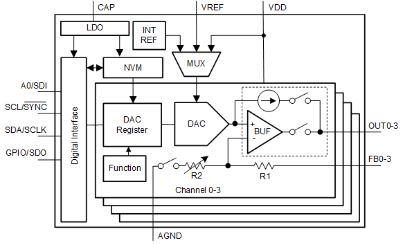
12 ビット DAC63004 および 10 ビット DAC53004 (DACx3004) は、超低消費電力、クワッド・チャネル、バッファ付き、電圧出力および電流出力のスマート D/A コンバータ (DAC) のピン互換ファミリです。DACx3004 は、ハイ・インピーダンスのパワーダウン・モードと、電源オフ状態中のハイ・インピーダンス出力をサポートしています。DAC 出力は、プログラマブルなコンパレータおよび電流シンクとして使用するためのフォース・センス・オプションを備えています。このスマート DAC は、多機能 GPIO、関数生成、NVM によって、プロセッサレス・アプリケーションや設計の再利用を実現できます。I2C、PMBus、SPI インターフェイスを自動的に検出します。また、内部リファレンスを搭載しています。
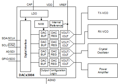
このスマート DAC は、小型パッケージおよび超低消費電力という特長を備えており、陸上移動無線、パルスオキシメータ (血中酸素飽和度計)、ノート PC 、その他バッテリ動作によるバイアス、キャリブレーション、波形生成などのアプリケーションに最適です。
製品情報
| 部品番号 | パッケージ(1) | 本体サイズ (公称) |
|---|---|---|
| DACx3004 | WQFN (16) | 3.00mm × 3.00mm |
(1) 利用可能なパッケージについては、このデータシートの末尾にある注文情報を参照してください。
 ブロック概略図
 DACx3004 、陸上移動無線のバイアス用
4 Revision History
Changes from Revision * (April 2021) to Revision A (December 2021)
- DACx3004 デバイスを事前情報 (プレビュー) から量産データ (アクティブ) に変更Go
5 Pin Configuration and Functions
Figure 5-1 RTE Package, 16-pin WQFN, Top
View
Table 5-1 Pin Functions
| PIN | TYPE | DESCRIPTION | |
|---|---|---|---|
| NO. | NAME | ||
| 1 | FB3 | Input | Voltage feedback pin for channel 3. In voltage-output mode, connect to OUT3 for closed-loop amplifier output. In current-output mode, keep the FB3 pin unconnected to minimize leakage current. |
| 2 | OUT3 | Output | Analog output voltage from DAC channel 3. |
| 3 | OUT2 | Output | Analog output voltage from DAC channel 2. |
| 4 | FB2 | Input | Voltage feedback pin for channel 2. In voltage-output mode, connect to OUT2 for closed-loop amplifier output. In current-output mode, keep the FB2 pin unconnected to minimize leakage current. |
| 5 | GPIO/SDO | Input/Output | General-purpose input/output configurable as LDAC, PD, PROTECT, RESET, SDO, and STATUS. For STATUS and SDO, connect the pin to the IO voltage with an external pullup resistor. If unused, connect the GPIO pin to VDD or AGND using an external resistor. This pin can ramp up before VDD. |
| 6 | SCL/SYNC | Output | I2C serial interface clock or SPI chip select input. This pin must be connected to the IO voltage using an external pullup resistor. This pin can ramp up before VDD. |
| 7 | A0/SDI | Input | Address
configuration pin for I2C or serial data input for SPI.
For A0, connect this pin to VDD, AGND, SDA, or SCL for address configuration (Section 7.5.2.2.1). For SDI, this pin need not be pulled up or pulled down. This pin can ramp up before VDD. |
| 8 | SDA/SCLK | Input/Output | Bidirectional I2C serial data bus or SPI clock input. This pin must be connected to the IO voltage using an external pullup resistor in the I2C mode. This pin can ramp up before VDD. |
| 9 | FB1 | Input | Voltage feedback pin for channel 1. In voltage-output mode, connect to OUT1 for closed-loop amplifier output. In current-output mode, keep the FB1 pin unconnected to minimize leakage current. |
| 10 | OUT1 | Output | Analog output voltage from DAC channel 1. |
| 11 | OUT0 | Output | Analog output voltage from DAC channel 0. |
| 12 | FB0 | Input | Voltage feedback pin for channel 0. In voltage-output mode, connect to OUT0 for closed-loop amplifier output. In current-output mode, keep the FB0 pin unconnected to minimize leakage current. |
| 13 | CAP | Power | External bypass capacitor for the internal LDO. Connect a capacitor (approximately 1.5 μF) between CAP and AGND. |
| 14 | AGND | Ground | Ground reference point for all circuitry on the device. |
| 15 | VDD | Power | Supply voltage. |
| 16 | VREF | Power | External
reference input. Connect a capacitor (approximately 0.1 μF) between
VREF and AGND. Use a pullup resistor to VDD when the external reference is not used. This pin must not ramp up before VDD. In case an external reference is used, make sure the reference ramps up after VDD. |
| — | Thermal Pad | Ground | Connect the thermal pad to AGND. |