SBAS439C August   2008  – July 2015 DAC8311 , DAC8411

PRODUCTION DATA.  

  1. Features
  2. Applications
  3. Description
  4. Revision History
  5. Device Comparison
  6. Pin Configuration and Functions
  7. Specifications
    1. 7.1 Absolute Maximum Ratings
    2. 7.2 ESD Ratings
    3. 7.3 Recommended Operating Conditions
    4. 7.4 Thermal Information
    5. 7.5 Electrical Characteristics
    6. 7.6 Timing Requirements: 14-Bit
    7. 7.7 Timing Requirements: 16-Bit
    8. 7.8 Typical Characteristics
      1. 7.8.1 Typical Characteristics: AVDD = 5 V
      2. 7.8.2 Typical Characteristics: AVDD = 3.6 V
      3. 7.8.3 Typical Characteristics: AVDD = 2.7 V
  8. Detailed Description
    1. 8.1 Overview
    2. 8.2 Functional Block Diagram
    3. 8.3 Feature Description
      1. 8.3.1 DAC Section
      2. 8.3.2 Resistor String
      3. 8.3.3 Output Amplifier
      4. 8.3.4 Power-On Reset to Zero-Scale
    4. 8.4 Device Functional Modes
      1. 8.4.1 Power-Down Modes
    5. 8.5 Programming
      1. 8.5.1 DAC8311 Serial Interface
        1. 8.5.1.1 DAC8311 Input Shift Register
        2. 8.5.1.2 DAC8311 SYNC Interrupt
      2. 8.5.2 DAC8411 Serial Interface
        1. 8.5.2.1 DAC8411 Input Shift Register
        2. 8.5.2.2 DAC8411 SYNC Interrupt
  9. Application and Implementation
    1. 9.1 Application Information
      1. 9.1.1 Microprocessor Interfacing
        1. 9.1.1.1 DAC8x11 to 8051 Interface
        2. 9.1.1.2 DAC8x11 to Microwire Interface
        3. 9.1.1.3 DAC8x11 to 68HC11 Interface
    2. 9.2 Typical Applications
      1. 9.2.1 Loop Powered Transmitter
        1. 9.2.1.1 Design Requirements
        2. 9.2.1.2 Detailed Design Procedure
        3. 9.2.1.3 Application Curves
      2. 9.2.2 Using the REF5050 as a Power Supply for the DAC8x11
      3. 9.2.3 Bipolar Operation Using the DAC8x11
  10. 10Power Supply Recommendations
  11. 11Layout
    1. 11.1 Layout Guidelines
    2. 11.2 Layout Example
  12. 12Device and Documentation Support
    1. 12.1 Related Links
    2. 12.2 Community Resources
    3. 12.3 Trademarks
    4. 12.4 Electrostatic Discharge Caution
    5. 12.5 Glossary
  13. 13Mechanical, Packaging, and Orderable Information

パッケージ・オプション

メカニカル・データ(パッケージ|ピン)
サーマルパッド・メカニカル・データ

6 Pin Configuration and Functions

DCK Package
6-Pin SC70
Top View
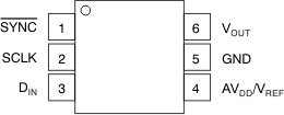
DAC8311 DAC8411 po_bas439.gif

Pin Functions

PIN I/O DESCRIPTION
NAME NO.
AVDD/VREF 4 I Power Supply Input, +2 V to +5.5 V.
DIN 3 I Serial Data Input. Data is clocked into the 24-bit (DAC8411) or 16-bit (DAC8311) input shift register on the falling edge of the serial clock input.
GND 5 Ground reference point for all circuitry on the part.
SCLK 2 I Serial Clock Input. Data can be transferred at rates up to 50 MHz.
SYNC 1 I Level-triggered control input (active low). This is the frame sychronization signal for the input data. When SYNC goes low, it enables the input shift register and data are transferred in on the falling edges of the following clocks. The DAC is updated following the 24th (DAC8411) or 16th (DAC8311) clock cycle, unless SYNC is taken high before this edge, in which case the rising edge of SYNC acts as an interrupt and the write sequence is ignored by the DAC8x11. Refer to the DAC8311 and DAC8411SYNC Interrupt sections for more details.
VOUT 6 O Analog output voltage from DAC. The output amplifier has rail-to-rail operation.