JAJSKY2B November 2017 – November 2024 DLP650LE
PRODUCTION DATA
- 1
- 1 特長
- 2 アプリケーション
- 3 概要
- 4 Pin Configuration and Functions
-
5 Specifications
- 5.1 Absolute Maximum Ratings
- 5.2 Storage Conditions
- 5.3 ESD Ratings
- 5.4 Recommended Operating Conditions
- 5.5 Thermal Information
- 5.6 Electrical Characteristics
- 5.7 Capacitance at Recommended Operating Conditions
- 5.8 Timing Requirements
- 5.9 Window Characteristics
- 5.10 System Mounting Interface Loads
- 5.11 Micromirror Array Physical Characteristics
- 5.12 Micromirror Array Optical Characteristics
- 5.13 Chipset Component Usage Specification
- 6 Detailed Description
- 7 Application and Implementation
- 8 Power Supply Recommendations
- 9 Device and Documentation Support
- 10Revision History
- 11Mechanical, Packaging, and Orderable Information
3 概要
テキサス・インスツルメンツ DLP® DLP650LE デジタル マイクロミラー デバイス (DMD) は、デジタル制御型の MEMS (micro-electromechanical system) 空間光変調器 (SLM) で、色鮮やかな WXGA ディスプレイ ソリューションを低コストで実現します。DLP650LE DMD は、DLPC4420 ディスプレイ コントローラ、DLPA100 電源およびモーター ドライバ、DLPA200 DMD マイクロミラー ドライバと組み合わせて使用すると、高性能システムを実現できます。16:10 の広いアスペクト比、高輝度、システムの簡素化を必要とするディスプレイ アプリケーションに最適です。DLP650LE DMD は、DLPC4430 をディスプレイ コントローラとして使用することもできます。
DMD のエコシステムに、設計期間の短縮に役立つ定評あるリソースが用意されています。承認済みの光学モジュール メーカーやサード パーティー プロバイダを探すには、DLP® Products サード パーティー プロバイダ検索ツールをご利用ください。
DMD を使用して設計を始める方法の詳細については、『テキサス・インスツルメンツの DLP ディスプレイ テクノロジーを使用した設計の開始』をご覧ください。
製品情報
| 部品番号 | パッケージ(1) | パッケージ サイズ |
|---|---|---|
| DLP650LE | FYL (149) | 32.20mm × 22.30mm |
(1) 利用可能なすべてのパッケージについては、データシートの末尾にある注文情報を参照してください。
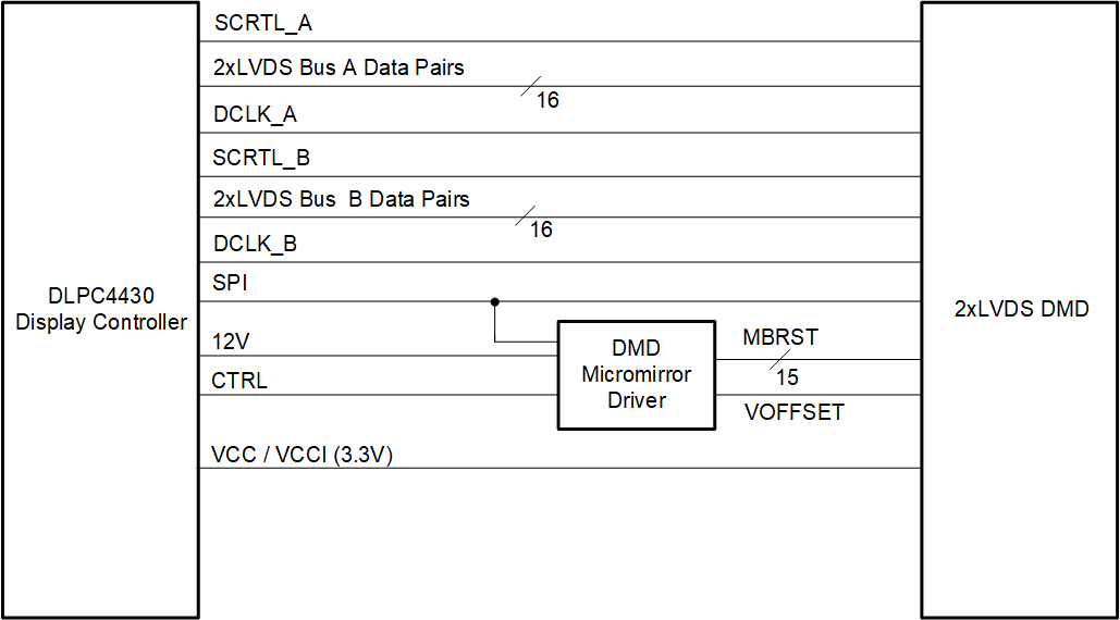
 DLP650LE のアプリケーション概略図