JAJSPO7C March 2015 – January 2023 DRV2700
PRODUCTION DATA
- 1 特長
- 2 アプリケーション
- 3 概要
- 4 Revision History
- 5 Pin Configuration and Functions
- 6 Specifications
- 7 Detailed Description
-
8 Application and Implementation
- 8.1 Application Information
- 8.2
Typical Applications
- 8.2.1
AC-Coupled DAC Input Application
- 8.2.1.1 Design Requirements
- 8.2.1.2
Detailed Design Procedure
- 8.2.1.2.1 Piezo Load Selection
- 8.2.1.2.2 Programming The Boost Voltage
- 8.2.1.2.3 Inductor and Transformer Selection
- 8.2.1.2.4 Programing the Boost and Flyback Current-Limit
- 8.2.1.2.5 Boost Capacitor Selection
- 8.2.1.2.6 Pulldown FET and Resistors
- 8.2.1.2.7 Low-Voltage Operation
- 8.2.1.2.8 Current Consumption Calculation
- 8.2.1.2.9 Input Filter Considerations
- 8.2.1.2.10 Output Limiting Factors
- 8.2.1.2.11 Startup and Shutdown Sequencing
- 8.2.1.3 Application Curves
- 8.2.2 Filtered AC Coupled Single-Ended PWM Input Application
- 8.2.3 DC-Coupled DAC Input Application
- 8.2.4 DC-Coupled Reference Input Application
- 8.2.5 Flyback Circuit
- 8.2.1
AC-Coupled DAC Input Application
- 8.3 System Example
- 9 Power Supply Recommendations
- 10Layout
- 11Device and Documentation Support
- 12Mechanical, Packaging, and Orderable Information
パッケージ・オプション
デバイスごとのパッケージ図は、PDF版データシートをご参照ください。
メカニカル・データ(パッケージ|ピン)
- RGP|20
サーマルパッド・メカニカル・データ
- RGP|20
発注情報
3 概要
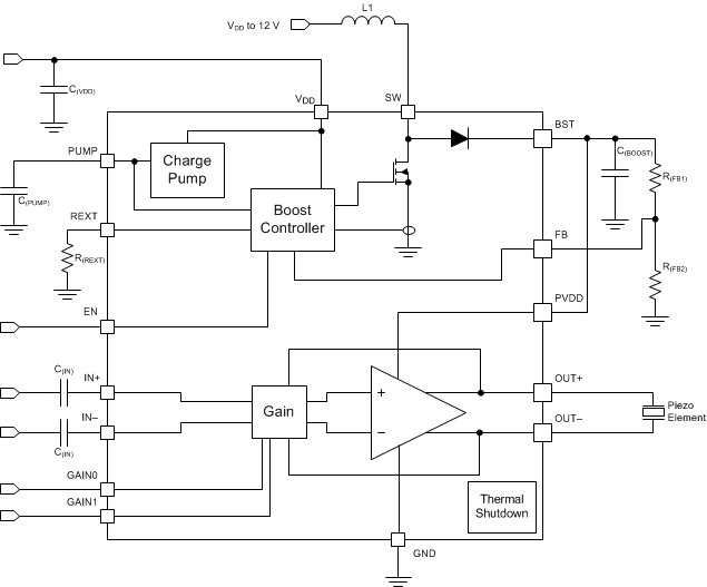
DRV2700 デバイスは、105V の昇圧スイッチ、パワー・ダイオード、完全差動アンプを内蔵したシングルチップのピエゾ・ドライバです。この多用途デバイスは、高電圧と低電圧の両方の圧電性負荷を駆動できます。入力信号は、差動またはシングルエンドで、AC 結合または DC 結合が可能です。DRV2700 デバイスは、以下の 4 つの GPIO 制御ゲインをサポートしています。28.8dB、34.8dB、38.4dB、および 40.7dB。
昇圧電圧は、2 つの外付け抵抗を使用して設定します。スイッチ・ピン (SW) と VDD ピンに印加される電圧は、個別のバッテリに対応するために分離されています。昇圧電流制限は、R(REXT) 抵抗によりプログラム可能です。昇圧コンバータ・アーキテクチャにより、ユーザーは希望の性能要件に基づき、特定のインダクタに合わせて DRV2700 回路を最適化できます。また、この昇圧コンバータはヒステリシス・アーキテクチャをベースにしており、スイッチング損失を最小限に抑えて効率を向上させます。
DRV2700 デバイスは標準のスタートアップ時間が 1.5ms で、スリープから素早く復帰するのに理想的なピエゾ・ドライバです。過熱保護機能により、過駆動時の損傷からデバイスを保護しています。
デバイス情報
| デバイス名(1) | パッケージ | 本体サイズ (公称) |
|---|---|---|
| DRV2700 | VQFN (20) | 4.00mm × 4.00mm |
(1) 利用可能なすべてのパッケージについては、このデータシートの末尾にある注文情報を参照してください。
 簡略回路図
簡略回路図