JAJSDU1 August 2017 DRV5012
PRODUCTION DATA.
- 1 特長
- 2 アプリケーション
- 3 概要
- 4 改訂履歴
- 5 Pin Configuration and Functions
- 6 Specifications
- 7 Detailed Description
- 8 Application and Implementation
- 9 Power Supply Recommendations
- 10Layout
- 11デバイスおよびドキュメントのサポート
- 12メカニカル、パッケージ、および注文情報
パッケージ・オプション
デバイスごとのパッケージ図は、PDF版データシートをご参照ください。
メカニカル・データ(パッケージ|ピン)
- DMR|4
サーマルパッド・メカニカル・データ
- DMR|4
発注情報
8 Application and Implementation
NOTE
Information in the following applications sections is not part of the TI component specification, and TI does not warrant its accuracy or completeness. TI’s customers are responsible for determining suitability of components for their purposes. Customers should validate and test their design implementation to confirm system functionality.
8.1 Application Information
The DRV5012 device is typically used in rotary applications for brushless DC (BLDC) motor sensors or incremental rotary encoding.
To ensure reliable functionality, the magnet should apply a flux density at the sensor greater than the maximum BOP and less than the minimum BRP thresholds. It is good practice to add additional margin to account for mechanical tolerance, temperature effects, and magnet variation.
8.2 Typical Applications
8.2.1 BLDC Motor Sensors Application
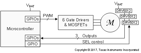
 Figure 13. BLDC Motor System
8.2.1.1 Design Requirements
For this design example, use the parameters listed in Table 1.
Table 1. Design Parameters
| DESIGN PARAMETER | EXAMPLE VALUE |
|---|---|
| Number of motor phases | 3 |
| Motor RPM | 3000 |
| Number of magnet poles on the rotor | 6 |
| Magnetic material | Bonded Neodymium |
| Peak magnetic flux density at the Hall sensors | ±15 mT |
| Battery voltage range (VBAT) | 2 to 3.5 V |
8.2.1.2 Detailed Design Procedure
Three-phase brushless DC motors often use 3 Hall effect latch devices to measure the electrical angle of the rotor and tell the controller how to drive the 3 wires. These wires connect to electromagnet windings, which generate magnetic fields that apply forces to the permanent magnets on the rotor.
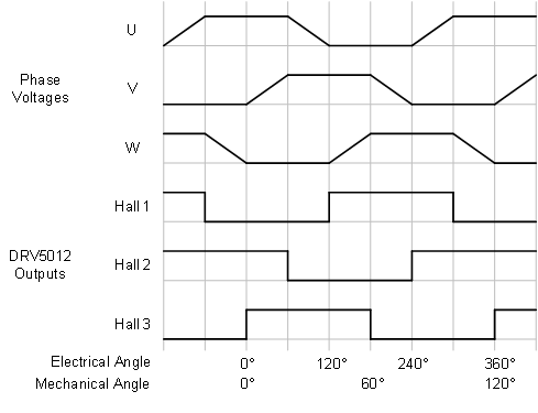
The 3 Hall sensors should be spaced across the printed-circuit board (PCB) so that they are 120° electrical degrees apart. This configuration creates six 3-bit states with equal time duration for each electrical cycle, which consists of 1 north and 1 south magnetic pole. From the center of the motor axis, the number of degrees each sensor should be spaced equals 2 / [number of poles] × 120°. In this design example, 1 sensor is placed at 0°, 1 sensor is placed 40° rotated, and 1 sensor is placed 80° rotated. Alternatively, a 3× degree offset can be added or subtracted to any sensor, meaning the third sensor could alternatively be placed at
80° – (3 × 40°) = –40°.
While an ideal BLDC motor would energize the phases at the exact correct times, the DRV5012 device introduces variable lag because of the sampling architecture that achieves low power. An acceptable amount of lag can be measured by the sampling time error as a percentage of the electrical period. This design example uses 3000 RPM, which is 50 revolutions per second. Each revolution has 6 poles (3 electrical cycles), so the electrical frequency is 150 Hz, a period of 6.7 ms. The DRV5012 device in 2.5 kHz mode has a sampling period of 0.4 ms, which is 6% of the electrical period. Generally, the maximum timing error should be kept under 10% to ensure the BLDC motor spins, and timing error can reduce motor efficiency.
When the motor in this example is not driven, the SEL pins of the DRV5012 devices are set to a low voltage, and the sensor outputs are monitored for changes. If a change occurs, the microcontroller wakes the system into a higher power state and takes other appropriate action.
8.2.1.3 Application Curve
 Figure 14. 3-Phase BLDC Motor Phase Voltages and Hall Signals
8.2.2 Incremental Rotary Encoding Application
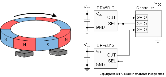
 Figure 15. Incremental Rotary Encoding System
8.2.2.1 Design Requirements
For this design example, use the parameters listed in Table 2.
Table 2. Design Parameters
| DESIGN PARAMETER | EXAMPLE VALUE |
|---|---|
| RPM range | 0 to 4000 |
| Number of magnet poles | 8 |
| Magnetic material | Ferrite |
| Air gap above the Hall sensors | 2.5 mm |
| Peak magnetic flux density at the sensors | ±7 mT |
8.2.2.2 Detailed Design Procedure
Incremental encoders are used on knobs, wheels, motors, and flow meters to measure relative rotary movement. By attaching a ring magnet to the rotating component and placing a DRV5012 device nearby, the sensor generates voltage pulses as the magnet turns. If directional information is also needed (clockwise versus counterclockwise), a second DRV5012 device can be added with a phase offset, and then the order of transitions between the two signals describes the direction.
Creating this phase offset requires spacing the two sensors apart on the PCB, and an ideal 90° quadrature offset is attained when the sensors are separated by half the length of each magnet pole, plus any integer number of pole lengths. Figure 15 shows this configuration, as the sensors are 1.5 pole lengths apart. One of the sensors changes its output every 360° / 8 poles / 2 sensors = 22.5° of rotation. For reference, the TI Design TIDA-00480 uses a 66-pole magnet with changes every 2.7°.
Because the DRV5012 device periodically samples the magnetic field, there is a limit to the maximum rotational speed that can be measured. Generally, the device sampling rate should be faster than 2 times the number of poles per second. In this design example, the maximum speed is 4000 RPM, which involves 533 poles per second. The DRV5012 has a minimum sampling frequency of 1665 Hz (when the SEL pin is high), which is approximately 3 × 533 poles per second.
In systems where the sensor sampling rate is close to 2 times the number of poles per second, most of the samples will measure a magnetic field that is significantly lower than the peak value, since the peaks only occur when the sensor and pole are perfectly aligned. In this case, margin should be added by applying a stronger magnetic field that has peaks significantly higher than the maximum BOP of the DRV5012 device.
8.2.2.3 Application Curve
Two signals in quadrature provide movement and direction information. Each 2-bit state has unique adjacent
2-bit states for clockwise and counterclockwise.
 Figure 16. 2-bit Quadrature Output
8.3 Do's and Don'ts
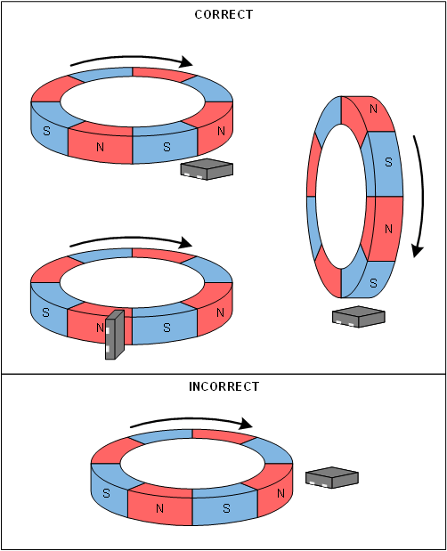
Because the Hall element is sensitive to magnetic fields that are perpendicular to the top of the package, a correct magnet orientation must be used for the sensor to detect the field. Figure 17 shows correct and incorrect orientations when using a ring magnet.
 Figure 17. Correct and Incorrect Magnet Orientations