JAJSL26B January 2021 – April 2022 DRV8316
PRODUCTION DATA
- 1 特長
- 2 アプリケーション
- 3 概要
- 4 Revision History
- 5 Device Comparison Table
- 6 Pin Configuration and Functions
- 7 Specifications
-
8 Detailed Description
- 8.1 Overview
- 8.2 Functional Block Diagram
- 8.3
Feature Description
- 8.3.1 Output Stage
- 8.3.2 Control Modes
- 8.3.3 Device Interface Modes
- 8.3.4 Step-Down Mixed-Mode Buck Regulator
- 8.3.5 AVDD Linear Voltage Regulator
- 8.3.6 Charge Pump
- 8.3.7 Slew Rate Control
- 8.3.8 Cross Conduction (Dead Time)
- 8.3.9 Propagation Delay
- 8.3.10 Pin Diagrams
- 8.3.11 Current Sense Amplifiers
- 8.3.12 Active Demagnetization
- 8.3.13 Cycle-by-Cycle Current Limit
- 8.3.14
Protections
- 8.3.14.1 VM Supply Undervoltage Lockout (NPOR)
- 8.3.14.2 AVDD Undervoltage Lockout (AVDD_UV)
- 8.3.14.3 BUCK Undervoltage Lockout (BUCK_UV)
- 8.3.14.4 VCP Charge Pump Undervoltage Lockout (CPUV)
- 8.3.14.5 Overvoltage Protections (OV)
- 8.3.14.6 Overcurrent Protection (OCP)
- 8.3.14.7 Buck Overcurrent Protection
- 8.3.14.8 Thermal Warning (OTW)
- 8.3.14.9 Thermal Shutdown (OTS)
- 8.4 Device Functional Modes
- 8.5 SPI Communication
- 8.6 Register Map
- 9 Application and Implementation
- 10Power Supply Recommendations
- 11Layout
- 12Device and Documentation Support
- 13Mechanical, Packaging, and Orderable Information
パッケージ・オプション
メカニカル・データ(パッケージ|ピン)
- RGF|40
サーマルパッド・メカニカル・データ
- RGF|40
発注情報
8.3.12.1.1 Automatic Synchronous Rectification in Commutation
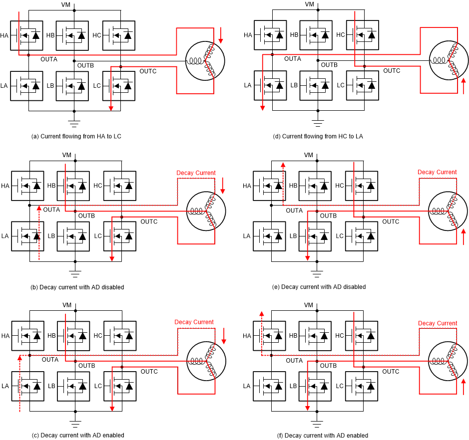
Figure 8-31 shows the operation of active demagnetization during the BLDC motor commutation. As shown in Figure 8-31 (a), the current is flowing from HA to LC in one commutation state. During the commutation changeover as shown in Figure 8-31 (b), the HC switch is turned on, whereas the commutation current (due to motor inductance) in OUTA flows through the body diode of LA. This incorporates a higher diode loss depending on the commutation current. This commutation loss is reduced by turning on the LA for the commutation time as shown in Figure 8-31 (c).
Similarly the operation of high-side FET is realized in Figure 8-31 (d), (e) and (f).
 Figure 8-31 ASR in BLDC Motor Commutation
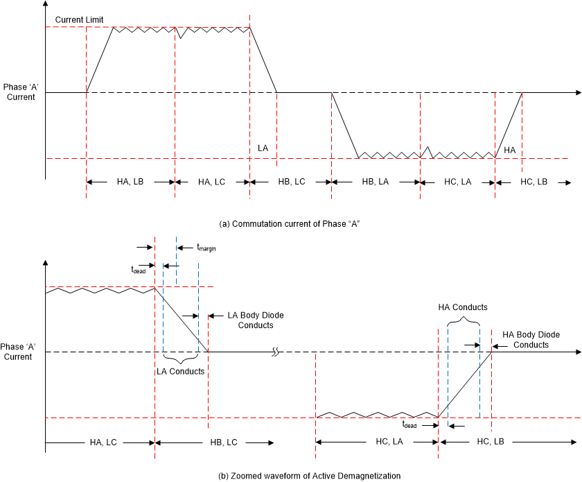
Figure 8-32 (a) shows the BLDC motor phase current waveforms for automatic synchronous rectification mode in BLDC motor operating with trapezoidal commutation. This figure shows the operation of various switches in a single commutation cycle.
Figure 8-32 (b) shows the zoomed waveform of commutation cycle with details on the ASR mode start with margin time (tmargin) and ASR mode early stop due to active demag. comparator threshold and delays.
 Figure 8-32 Current Waveforms for ASR in BLDC Motor Commutation