JAJSPA5 July   2020 DRV8353M

PRODUCTION DATA  

  1. 特長
  2. アプリケーション
  3. 概要
  4. Revision History
  5. Device Comparison Table
  6. Pin Configuration and Functions
    1.     Pin Functions—40-Pin DRV8353M Devices
  7. Absolute Maximum Ratings
  8. ESD Ratings
  9. Recommended Operating Conditions
  10. 10Thermal Information
  11. 11Electrical Characteristics
  12. 12SPI Timing Requirements
  13. 13Detailed Description
    1. 13.1 Overview
    2. 13.2 Functional Block Diagram
    3. 13.3 Feature Description
      1. 13.3.1 Three Phase Smart Gate Drivers
        1. 13.3.1.1 PWM Control Modes
          1. 13.3.1.1.1 6x PWM Mode (PWM_MODE = 00b or MODE Pin Tied to AGND)
          2. 13.3.1.1.2 3x PWM Mode (PWM_MODE = 01b or MODE Pin = 47 kΩ to AGND)
          3. 13.3.1.1.3 1x PWM Mode (PWM_MODE = 10b or MODE Pin = Hi-Z)
          4. 13.3.1.1.4 Independent PWM Mode (PWM_MODE = 11b or MODE Pin Tied to DVDD)
        2. 13.3.1.2 Device Interface Modes
          1. 13.3.1.2.1 Serial Peripheral Interface (SPI)
          2. 13.3.1.2.2 Hardware Interface
        3. 13.3.1.3 Gate Driver Voltage Supplies and Input Supply Configurations
        4. 13.3.1.4 Smart Gate Drive Architecture
          1. 13.3.1.4.1 IDRIVE: MOSFET Slew-Rate Control
          2. 13.3.1.4.2 TDRIVE: MOSFET Gate Drive Control
          3. 13.3.1.4.3 Propagation Delay
          4. 13.3.1.4.4 MOSFET VDS Monitors
          5. 13.3.1.4.5 VDRAIN Sense and Reference Pin
      2. 13.3.2 DVDD Linear Voltage Regulator
      3. 13.3.3 Pin Diagrams
      4. 13.3.4 Low-Side Current-Shunt Amplifiers
        1. 13.3.4.1 Bidirectional Current Sense Operation
        2. 13.3.4.2 Unidirectional Current Sense Operation (SPI only)
        3. 13.3.4.3 Amplifier Calibration Modes
        4. 13.3.4.4 MOSFET VDS Sense Mode (SPI Only)
      5. 13.3.5 Gate Driver Protective Circuits
        1. 13.3.5.1 VM Supply and VDRAIN Undervoltage Lockout (UVLO)
        2. 13.3.5.2 VCP Charge-Pump and VGLS Regulator Undervoltage Lockout (GDUV)
        3. 13.3.5.3 MOSFET VDS Overcurrent Protection (VDS_OCP)
          1. 13.3.5.3.1 VDS Latched Shutdown (OCP_MODE = 00b)
          2. 13.3.5.3.2 VDS Automatic Retry (OCP_MODE = 01b)
          3. 13.3.5.3.3 VDS Report Only (OCP_MODE = 10b)
          4. 13.3.5.3.4 VDS Disabled (OCP_MODE = 11b)
        4. 13.3.5.4 VSENSE Overcurrent Protection (SEN_OCP)
          1. 13.3.5.4.1 VSENSE Latched Shutdown (OCP_MODE = 00b)
          2. 13.3.5.4.2 VSENSE Automatic Retry (OCP_MODE = 01b)
          3. 13.3.5.4.3 VSENSE Report Only (OCP_MODE = 10b)
          4. 13.3.5.4.4 VSENSE Disabled (OCP_MODE = 11b or DIS_SEN = 1b)
        5. 13.3.5.5 Gate Driver Fault (GDF)
        6. 13.3.5.6 Overcurrent Soft Shutdown (OCP Soft)
        7. 13.3.5.7 Thermal Warning (OTW)
        8. 13.3.5.8 Thermal Shutdown (OTSD)
        9. 13.3.5.9 Fault Response Table
    4. 13.4 Device Functional Modes
      1. 13.4.1 Gate Driver Functional Modes
        1. 13.4.1.1 Sleep Mode
        2. 13.4.1.2 Operating Mode
        3. 13.4.1.3 Fault Reset (CLR_FLT or ENABLE Reset Pulse)
    5. 13.5 Programming
      1. 13.5.1 SPI Communication
        1. 13.5.1.1 SPI
          1. 13.5.1.1.1 SPI Format
    6. 13.6 Register Maps
      1. 13.6.1 Status Registers
        1. 13.6.1.1 Fault Status Register 1 (address = 0x00h)
        2. 13.6.1.2 Fault Status Register 2 (address = 0x01h)
      2. 13.6.2 Control Registers
        1. 13.6.2.1 Driver Control Register (address = 0x02h)
        2. 13.6.2.2 Gate Drive HS Register (address = 0x03h)
        3. 13.6.2.3 Gate Drive LS Register (address = 0x04h)
        4. 13.6.2.4 OCP Control Register (address = 0x05h)
        5. 13.6.2.5 CSA Control Register (address = 0x06h)
        6. 13.6.2.6 Driver Configuration Register (address = 0x07h)
  14. 14Application and Implementation
    1. 14.1 Application Information
    2. 14.2 Typical Application
      1. 14.2.1 Primary Application
        1. 14.2.1.1 Design Requirements
        2. 14.2.1.2 Detailed Design Procedure
          1. 14.2.1.2.1 External MOSFET Support
            1. 14.2.1.2.1.1 MOSFET Example
          2. 14.2.1.2.2 IDRIVE Configuration
            1. 14.2.1.2.2.1 IDRIVE Example
          3. 14.2.1.2.3 VDS Overcurrent Monitor Configuration
            1. 14.2.1.2.3.1 VDS Overcurrent Example
          4. 14.2.1.2.4 Sense-Amplifier Bidirectional Configuration
            1. 14.2.1.2.4.1 Sense-Amplifier Example
          5. 14.2.1.2.5 Single Supply Power Dissipation
          6. 14.2.1.2.6 Single Supply Power Dissipation Example
        3. 14.2.1.3 Application Curves
  15. 15Power Supply Recommendations
    1. 15.1 Bulk Capacitance Sizing
  16. 16Layout
    1. 16.1 Layout Guidelines
    2. 16.2 Layout Example
  17. 17Device and Documentation Support
    1. 17.1 Device Support
      1. 17.1.1 Device Nomenclature
    2. 17.2 Documentation Support
      1. 17.2.1 Related Documentation
    3. 17.3 ドキュメントの更新通知を受け取る方法
    4. 17.4 サポート・リソース
    5. 17.5 Trademarks
    6. 17.6 静電気放電に関する注意事項
    7. 17.7 用語集
  18. 18Mechanical, Packaging, and Orderable Information

パッケージ・オプション

メカニカル・データ(パッケージ|ピン)
サーマルパッド・メカニカル・データ
発注情報

概要

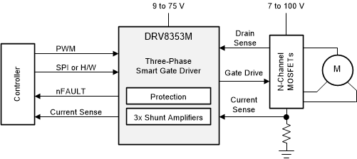
DRV8353M ファミリのデバイスは、3 相ブラシレス DC (BLDC) モータ・アプリケーション向けの高度に統合されたゲート・ドライバです。BLDC モータの磁界方向制御 (FOC)、正弦波電流制御、および台形電流制御に適しています。このデバイス・バリエーションにはオプションとして、各種のモータ制御方式をサポートするための内蔵電流シャント・アンプと、ゲート・ドライバや外部コントローラに給電するための降圧レギュレータが用意されています。

DRV8353M はスマート・ゲート・ドライブ (SGD) アーキテクチャを使用して、通常は MOSFET スルーレート制御および保護回路に必要となる外付け部品の数を減らしています。また、SGD アーキテクチャによりデッド・タイムが最適化されて貫通電流状況が防止され、MOSFET のスルーレート制御により電磁気干渉 (EMI) を柔軟に低減でき、VGS 監視によってゲートの短絡状況に対する保護を行えます。ゲートの強力なプルダウン回路は、望ましくない dV/dt 寄生ゲート・ターンオンの防止に役立ちます。

各種の PWM 制御モード (6x、3x、1x、および独立) がサポートされており、外部コントローラと簡単に接続できます。これらのモードにより、モータ・ドライバ PWM 制御信号のために必要なコントローラ出力の数を減らすことができます。このファミリのデバイスには 1x PWM モードも含まれており、内部ブロックの通信テーブルを使用して、BLDC モータの単純なセンサ付き台形制御に使用できます。

表 3-1 製品情報
部品番号パッケージ本体サイズ (公称)
DRV8353MWQFN (40)6.00mm×6.00mm
  1. 利用可能なパッケージについては、このデータシートの末尾にある注文情報を参照してください。
GUID-20200721-CA0I-2HQC-CS95-2TD2SVXLSWZJ-low.gif概略回路図