JAJSCQ3E October 2016 – January 2021 DRV8702-Q1 , DRV8703-Q1
PRODUCTION DATA
- 1 特長
- 2 アプリケーション
- 3 概要
- 4 Revision History
- 5 Pin Configuration and Functions
- 6 Specifications
-
7 Detailed Description
- 7.1 Overview
- 7.2 Functional Block Diagram
- 7.3
Feature Description
- 7.3.1 Bridge Control
- 7.3.2 MODE Pin
- 7.3.3 nFAULT Pin
- 7.3.4 Current Regulation
- 7.3.5 Amplifier Output (SO)
- 7.3.6 PWM Motor Gate Drivers
- 7.3.7 IDRIVE Pin (DRV8702-Q1 Only)
- 7.3.8 Dead Time
- 7.3.9 Propagation Delay
- 7.3.10 Overcurrent VDS Monitor
- 7.3.11 VDS Pin (DRV8702-Q1 Only)
- 7.3.12 Charge Pump
- 7.3.13 Gate Drive Clamp
- 7.3.14
Protection Circuits
- 7.3.14.1 VM Undervoltage Lockout (UVLO2)
- 7.3.14.2 Logic Undervoltage (UVLO1)
- 7.3.14.3 VCP Undervoltage Lockout (CPUV)
- 7.3.14.4 Overcurrent Protection (OCP)
- 7.3.14.5 Gate Driver Fault (GDF)
- 7.3.14.6 Thermal Shutdown (TSD)
- 7.3.14.7 Watchdog Fault (WDFLT, DRV8703-Q1 Only)
- 7.3.14.8 Reverse Supply Protection
- 7.3.15 Hardware Interface
- 7.4 Device Functional Modes
- 7.5 Programming
- 7.6 Register Maps
- 8 Application and Implementation
- 9 Power Supply Recommendations
- 10Layout
- 11Device and Documentation Support
- 12Mechanical, Packaging, and Orderable Information
パッケージ・オプション
デバイスごとのパッケージ図は、PDF版データシートをご参照ください。
メカニカル・データ(パッケージ|ピン)
- RHB|32
サーマルパッド・メカニカル・データ
発注情報
3 概要
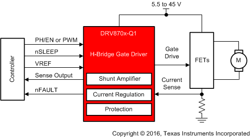
DRV870x-Q1 デバイスは、4 つの外部 N チャネル MOSFET を使用して双方向ブラシ付き DC モータを駆動できる、小型のシングル H ブリッジ・ゲート・ドライバです。
PH/EN、独立した H ブリッジ、または PWM インターフェイスにより、制御回路に容易に接続できます。内蔵の検出アンプによって電流制御機能を調整できます。内蔵のチャージ・ポンプにより 100% デューティ・サイクルがサポートされ、外部の逆極性バッテリ・スイッチの駆動に使用できます。
独立のハーフ・ブリッジ・モードによりハーフ・ブリッジを共有し、複数の DC モータをシーケンシャルに、コスト効率の高い方法で制御できます。ゲート・ドライバには、オフ時間が固定された PWM 電流チョッピングにより巻線電流を調整するための回路が含まれています。
DRV870x-Q1 デバイスにはスマート・ゲート・ドライブ・テクノロジが含まれているため、外部のゲート部品 (抵抗やツェナー・ダイオード) を必要とせず、外部 FET を保護できます。スマート・ゲート・ドライブ・アーキテクチャはデッドタイムを最適化することで貫通電流状況を回避し、プログラム可能なスルーレート制御により電磁気干渉 (EMI) を柔軟に低減し、いかなるゲート短絡状況からも保護を行えます。さらに、アクティブおよびパッシブ・プルダウンが組み込まれており、あらゆる dv/dt ゲート・ターンオンを防止できます。
| 部品番号 | パッケージ | 本体サイズ (公称) |
|---|---|---|
| DRV8702-Q1 | VQFN (32) | 5.00mm × 5.00mm |
| DRV8703-Q1 |
 概略回路図
概略回路図