JAJS707E January   2001  – January 2018 DS92LV040A

PRODUCTION DATA.  

  1. 特長
  2. アプリケーション
  3. 概要
    1.     概略機能図
  4. 改訂履歴
  5. Pin Configuration and Functions
    1.     Pin Functions
  6. Specifications
    1. 6.1 Absolute Maximum Ratings
    2. 6.2 ESD Ratings
    3. 6.3 Recommended Operating Conditions
    4. 6.4 Thermal Information
    5. 6.5 DC Electrical Characteristics
    6. 6.6 AC Electrical Characteristics
  7. Parameter Measurement Information
    1. 7.1 Test Circuits and Timing Waveforms
  8. Detailed Description
    1. 8.1 Overview
    2. 8.2 Functional Block Diagram
    3. 8.3 Feature Description
    4. 8.4 Device Functional Modes
  9. Application and Implementation
    1. 9.1 Application Information
    2. 9.2 Typical Application
      1. 9.2.1 Multipoint Communications
      2. 9.2.2 Design Requirements
      3. 9.2.3 Detailed Design Procedure
        1. 9.2.3.1 Supply Voltage
        2. 9.2.3.2 Supply Bypass Capacitance
        3. 9.2.3.3 Termination Resistors
        4. 9.2.3.4 Interconnecting Media
  10. 10Power Supply Recommendations
  11. 11Layout
    1. 11.1 Layout Guidelines
      1. 11.1.1 Microstrip vs. Stripline Topologies
      2. 11.1.2 Dielectric Type and Board Construction
      3. 11.1.3 Recommended Stack Layout
      4. 11.1.4 Separation Between Traces
      5. 11.1.5 Crosstalk and Ground Bounce Minimization
      6. 11.1.6 Decoupling
    2. 11.2 Layout Example
  12. 12デバイスおよびドキュメントのサポート
    1. 12.1 ドキュメントのサポート
      1. 12.1.1 関連資料
    2. 12.2 ドキュメントの更新通知を受け取る方法
    3. 12.3 コミュニティ・リソース
    4. 12.4 商標
    5. 12.5 静電気放電に関する注意事項
    6. 12.6 Glossary
  13. 13メカニカル、パッケージ、および注文情報

パッケージ・オプション

メカニカル・データ(パッケージ|ピン)
サーマルパッド・メカニカル・データ
発注情報

Multipoint Communications

In a multipoint configuration many transmitters and many receivers can be interconnected on a single transmission line. The key difference compared to multi-drop is the presence of two or more drivers. Such a situation creates contention issues that need not be addressed with point-to-point or multidrop systems. Multipoint operation allows for bidirectional, half-duplex communication over a single balanced media pair. To support the location of the various drivers throughout the transmission line, double termination of the transmission line is now necessary.

The major challenge that system designers encounter are the impedance discontinuities that device loading and device connections (stubs) introduce on the common bus. Matching the impedance of the loaded bus and using signal drivers with controlled signal edges are the keys to error-free signal transmissions in multipoint topologies.

DS92LV040A bidirectional_SNOS521.gifFigure 10. Bidirectional Half-Duplex Point-to-Point Applications
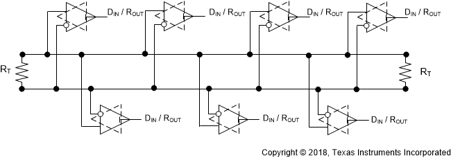
DS92LV040A multi_point_SNOS521.gifFigure 11. Multi-Point Bus Applications