JAJSFS6F
February 2012 – July 2018
HD3SS3412
PRODUCTION DATA.
1
特長
2
アプリケーション
3
概要
Device Images
HD3SS3412のピン配置
HD3SS3412スイッチのフロースルー配線
4
改訂履歴
5
概要(続き)
6
Pin Configuration and Functions
Pin Functions
7
Specifications
7.1
Absolute Maximum Ratings
7.2
ESD Ratings
7.3
Recommended Operating Conditions
7.4
Thermal Information
7.5
Electrical Characteristics
7.6
Dissipation Ratings
7.7
Typical Characteristics
8
Parameter Measurement Information
9
Detailed Description
9.1
Overview
9.2
Functional Block Diagram
9.3
Feature Description
9.4
Device Functional Modes
10
Application and Implementation
10.1
Application Information
10.1.1
AC Coupling Caps
10.2
Typical Application
10.2.1
Design Requirements
10.2.2
Detailed Design Procedure
10.2.3
Application Curves
11
Power Supply Recommendations
12
Layout
12.1
Layout Guidelines
12.2
Layout Example
13
デバイスおよびドキュメントのサポート
13.1
ドキュメントの更新通知を受け取る方法
13.2
コミュニティ・リソース
13.3
商標
13.4
静電気放電に関する注意事項
13.5
Glossary
14
メカニカル、パッケージ、および注文情報
パッケージ・オプション
メカニカル・データ(パッケージ|ピン)
RUA|42
MPQF210D
サーマルパッド・メカニカル・データ
RUA|42
QFND142D
発注情報
jajsfs6f_oa
jajsfs6f_pm
7.6
Dissipation Ratings
MIN
MAX
UNIT
P
D
Power Dissipation
2.8
4.4
mW
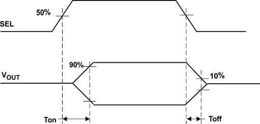
Figure 1.
Switch ON and OFF Timing Diagram
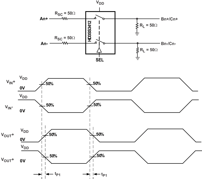
T
SKEWInter
= Difference between t
PD
for any two pairs of outputs
T
SKEWIntra
= Difference between t
P1
and t
P2
of same pair
Figure 2.
Propagation Delay Timing Diagram and Test Setup