SBOS508A December 2009 – December 2015 INA129-EP
PRODUCTION DATA.
7 Detailed Description
7.1 Overview
The INA129-EP instrumentation amplifier is a type of differential amplifier that has been outfitted with input protection circuit and input buffer amplifiers, which eliminate the need for input impedance matching and make the amplifier particularly suitable for use in measurement and test equipment. Additional characteristics of the INA129-EP include a very low DC offset, low drift, low noise, very high open-loop gain, very high common-mode rejection ratio, and very high input impedances. The INA129-EP is used where great accuracy and stability of the circuit both short and long-term are required.
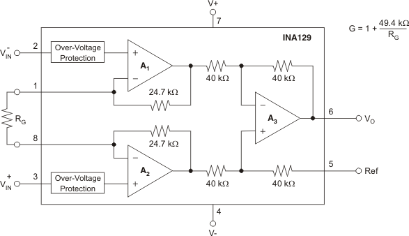
7.2 Functional Block Diagram

7.3 Feature Description
The INA129-EP device is a low power, general-purpose instrumentation amplifier that offers excellent accuracy. The versatile three-operational-amplifier design and small size make the amplifier ideal for a wide range of applications. Current-feedback input circuitry provides wide bandwidth, even at high gain. A single external resistor sets any gain from 1 to 10,000. The INA129-EP device is laser trimmed for very low offset voltage (50 μV) and high common-mode rejection (93 dB at G ≥ 100). This device operates with power supplies as low as ±2.25 V, and quiescent current of 2 mA, typically. The internal input protection can withstand up to ±40 V without damage.
7.4 Device Functional Modes
A single external resistor sets the any gain from 1 to 10000. TI INA129-EP provides an industry standard gain equation, as highlighted in Figure 16.
7.4.1 Noise Performance
The INA129-EP provides very low noise in most applications. Low frequency noise is approximately 0.2 μVPP measured from 0.1 Hz to 10 Hz (G ≥ 100). This provides dramatically improved noise when compared to state-of-the-art chopper-stabilized amplifiers.

| G ≥ 100 | ||
7.4.2 Input Common-Mode Range
The linear input voltage range of the input circuitry of the INA129-EP is from approximately 1.4 V below the positive supply voltage to 1.7 V above the negative supply. As a differential input voltage causes the output voltage increase, however, the linear input range will be limited by the output voltage swing of amplifiers A1 and A2. So the linear common-mode input range is related to the output voltage of the complete amplifier. This behavior also depends on supply voltage (see Figure 5 and Figure 6).
Input-overload can produce an output voltage that appears normal. For example, if an input overload condition drives both input amplifiers to their positive output swing limit, the difference voltage measured by the output amplifier will be near zero. The output of A3 will be near 0 V even though both inputs are overloaded.