JAJSD36 April 2017 INA233
PRODUCTION DATA.
- 1 特長
- 2 アプリケーション
- 3 概要
- 4 改訂履歴
- 5 Pin Configuration and Functions
- 6 Specifications
-
7 Detailed Description
- 7.1 Overview
- 7.2 Functional Block Diagram
- 7.3 Feature Description
- 7.4 Device Functional Modes
- 7.5 Programming
- 7.6
Register Maps
- 7.6.1 PMBus Command Support
- 7.6.2
Standard PMBus Commands
- 7.6.2.1 CLEAR_FAULTS (03h)
- 7.6.2.2 RESTORE_DEFAULT_ALL (12h)
- 7.6.2.3 CAPABILITY (19h)
- 7.6.2.4 IOUT_OC_WARN_LIMIT (4Ah) [default = 01111111 11111000]
- 7.6.2.5 VIN_OV_WARN_LIMIT (57h) [default = 01111111 11111000]
- 7.6.2.6 VIN_UV_WARN_LIMIT (58h) [default = 00000000 00000000]
- 7.6.2.7 PIN_OP_WARN_LIMIT (6Bh) [default = 11111111 11110000]
- 7.6.2.8 STATUS_BYTE (78h)
- 7.6.2.9 STATUS_WORD (79h)
- 7.6.2.10 STATUS_IOUT (7Bh)
- 7.6.2.11 STATUS_INPUT (7Ch)
- 7.6.2.12 STATUS_CML (7Eh)
- 7.6.2.13 STATUS_MFR_SPECIFIC (80h)
- 7.6.2.14 READ_EIN (86h)
- 7.6.2.15 READ_VIN (88h)
- 7.6.2.16 READ_IIN (89h)
- 7.6.2.17 READ_VOUT (8Bh)
- 7.6.2.18 READ_IOUT (8Ch, R)
- 7.6.2.19 READ_POUT (96h, R)
- 7.6.2.20 READ_PIN (97h, R)
- 7.6.2.21 MFR_ID (99h)
- 7.6.2.22 MFR_MODEL (9Ah)
- 7.6.2.23 MFR_REVISION (9Bh)
- 7.6.3
Manufacturer-Specific PMBus Commands
- 7.6.3.1 MFR_ADC_CONFIG (D0h) [default = 01000001 00100111]
- 7.6.3.2 MFR_READ_VSHUNT (D1h) [default = 00000000 00000000]
- 7.6.3.3 MFR_ALERT_MASK (D2h) [default = XXXXXXXX 11110000]
- 7.6.3.4 MFR_CALIBRATION (D4h) [default = 00000000 00000001]
- 7.6.3.5 MFR_DEVICE_CONFIG (D5h) [default = 00000010]
- 7.6.3.6 5.1.1 CLEAR_EIN (D6h)
- 7.6.3.7 TI_MFR_ID (E0h) [value = 01010100 01001001]
- 7.6.3.8 TI_MFR_MODEL (E1h) [value = 00110011 00110011]
- 7.6.3.9 TI_MFR_REVISION (E2h) [value = 01000001 00110000]
- 8 Application and Implementation
- 9 Power Supply Recommendations
- 10Layout
- 11デバイスおよびドキュメントのサポート
- 12メカニカル、パッケージ、および注文情報
10 Layout
10.1 Layout Guidelines
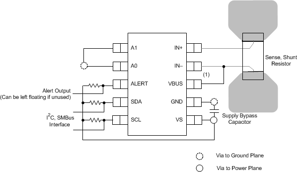
Connect the input pins (IN+ and IN–) to the sensing resistor using a Kelvin connection or a 4-wire connection. These connection techniques ensure that only the current-sensing resistor impedance is detected between the input pins. Poor routing of the current-sensing resistor commonly results in additional resistance present between the input pins. Given the very low ohmic value of the current-sensing resistor, any additional high-current carrying impedance causes significant measurement errors. Place the power-supply bypass capacitor as close as possible to the supply and ground pins.
10.2 Layout Example

1. Connect the VBUS pin to the power-supply rail.
Figure 46. INA233 Layout Example