JAJSK30 November   2020 INA280-Q1

PRODUCTION DATA  

  1. 特長
  2. アプリケーション
  3. 概要
  4. Revision History
  5. Pin Configuration and Functions
  6. Specifications
    1. 6.1 Absolute Maximum Ratings
    2. 6.2 ESD Ratings
    3. 6.3 Recommended Operating Conditions
    4. 6.4 Thermal Information
    5. 6.5 Electrical Characteristics
    6. 6.6 Typical Characteristics
  7. Detailed Description
    1. 7.1 Overview
    2. 7.2 Functional Block Diagram
    3. 7.3 Feature Description
      1. 7.3.1 Amplifier Input Common-Mode Range
        1. 7.3.1.1 Input-Signal Bandwidth
        2. 7.3.1.2 Low Input Bias Current
        3. 7.3.1.3 Multiple Fixed Gain Outputs
        4. 7.3.1.4 Wide Supply Range
    4. 7.4 Device Functional Modes
      1. 7.4.1 Unidirectional Operation
      2. 7.4.2 High Signal Throughput
  8. Application and Implementation
    1. 8.1 Application Information
      1. 8.1.1 RSENSE and Device Gain Selection
      2. 8.1.2 Input Filtering
    2. 8.2 Typical Application
      1. 8.2.1 Design Requirements
      2. 8.2.2 Detailed Design Procedure
        1. 8.2.2.1 Overload Recovery With Negative VSENSE
      3. 8.2.3 Application Curve
  9. Power Supply Recommendations
  10. 10Layout
    1. 10.1 Layout Guidelines
    2. 10.2 Layout Example
  11. 11Device and Documentation Support
    1. 11.1 Documentation Support
      1. 11.1.1 Related Documentation
    2. 11.2 ドキュメントの更新通知を受け取る方法
    3. 11.3 サポート・リソース
    4. 11.4 Trademarks
    5. 11.5 静電気放電に関する注意事項
    6. 11.6 用語集
  12. 12Mechanical, Packaging, and Orderable Information

パッケージ・オプション

メカニカル・データ(パッケージ|ピン)
サーマルパッド・メカニカル・データ
発注情報

Unidirectional Operation

The INA280-Q1 measures the differential voltage developed by current flowing through a resistor that is commonly referred to as a current-sensing resistor or a current-shunt resistor. The INA280-Q1 operates in unidirectional mode only, meaning it only senses current sourced from a power supply to a system load as shown in Figure 7-3.
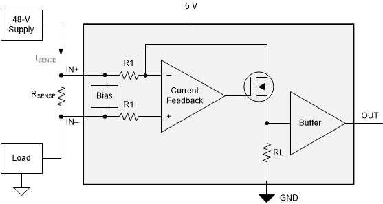
GUID-BAAA99BE-F36F-4A3C-A4C4-D76D8CFB32B8-low.gifFigure 7-3 Unidirectional Application

The linear range of the output stage is limited to how close the output voltage can approach ground under zero-input conditions. The zero current output voltage of the INA280-Q1 is very small, with a maximum of GND + 25 mV. Make sure to apply a sense voltage of (25 mV / Gain) or greater to keep the INA280-Q1 output in the linear region of operation.