-
L293x Quadruple Half-H Drivers
- 1 Features
- 2 Applications
- 3 Description
- 4 Revision History
- 5 Pin Configuration and Functions
- 6 Specifications
- 7 Parameter Measurement Information
- 8 Detailed Description
- 9 Application and Implementation
- 10Power Supply Recommendations
- 11Layout
- 12Device and Documentation Support
- 13Mechanical, Packaging, and Orderable Information
- IMPORTANT NOTICE
L293x Quadruple Half-H Drivers
1 Features
2 Applications
- Stepper Motor Drivers
- DC Motor Drivers
- Latching Relay Drivers
3 Description
The L293 and L293D devices are quadruple high-current half-H drivers. The L293 is designed to provide bidirectional drive currents of up to 1 A at voltages from 4.5 V to 36 V. The L293D is designed to provide bidirectional drive currents of up to 600-mA at voltages from 4.5 V to 36 V. Both devices are designed to drive inductive loads such as relays, solenoids, DC and bipolar stepping motors, as well as other high-current/high-voltage loads in positive-supply applications.
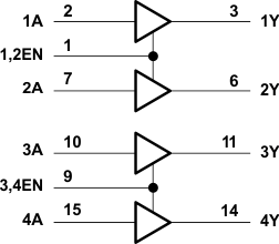
Each output is a complete totem-pole drive circuit, with a Darlington transistor sink and a pseudo- Darlington source. Drivers are enabled in pairs, with drivers 1 and 2 enabled by 1,2EN and drivers 3 and 4 enabled by 3,4EN.
The L293 and L293D are characterized for operation from 0°C to 70°C.
Device Information(1)
| PART NUMBER | PACKAGE | BODY SIZE (NOM) |
|---|---|---|
| L293NE | PDIP (16) | 19.80 mm × 6.35 mm |
| L293DNE | PDIP (16) | 19.80 mm × 6.35 mm |
- For all available packages, see the orderable addendum at the end of the data sheet.
Logic Diagram

4 Revision History
Changes from C Revision (November 2004) to D Revision
- Removed Ordering Information table Go
- Added ESD Ratings and Thermal Information tables, Feature Description section, Device Functional Modes, Application and Implementation section, Power Supply Recommendations section, Layout section, Device and Documentation Support section, and Mechanical, Packaging, and Orderable Information section. Go
5 Pin Configuration and Functions

Pin Functions
| PIN | TYPE | DESCRIPTION | |
|---|---|---|---|
| NAME | NO. | ||
| 1,2EN | 1 | I | Enable driver channels 1 and 2 (active high input) |
| <1:4>A | 2, 7, 10, 15 | I | Driver inputs, noninverting |
| <1:4>Y | 3, 6, 11, 14 | O | Driver outputs |
| 3,4EN | 9 | I | Enable driver channels 3 and 4 (active high input) |
| GROUND | 4, 5, 12, 13 | — | Device ground and heat sink pin. Connect to printed-circuit-board ground plane with multiple solid vias |
| VCC1 | 16 | — | 5-V supply for internal logic translation |
| VCC2 | 8 | — | Power VCC for drivers 4.5 V to 36 V |
6 Specifications
6.1 Absolute Maximum Ratings
over operating free-air temperature range (unless otherwise noted)(1)| MIN | MAX | UNIT | ||
|---|---|---|---|---|
| Supply voltage, VCC1(2) | 36 | V | ||
| Output supply voltage, VCC2 | 36 | V | ||
| Input voltage, VI | 7 | V | ||
| Output voltage, VO | –3 | VCC2 + 3 | V | |
| Peak output current, IO (nonrepetitive, t ≤ 5 ms): L293 | –2 | 2 | A | |
| Peak output current, IO (nonrepetitive, t ≤ 100 µs): L293D | –1.2 | 1.2 | A | |
| Continuous output current, IO: L293 | –1 | 1 | A | |
| Continuous output current, IO: L293D | –600 | 600 | mA | |
| Maximum junction temperature, TJ | 150 | °C | ||
| Storage temperature, Tstg | –65 | 150 | °C | |
6.2 ESD Ratings
| VALUE | UNIT | |||
|---|---|---|---|---|
| V(ESD) | Electrostatic discharge | Human-body model (HBM), per ANSI/ESDA/JEDEC JS-001(1) | ±2000 | V |
| Charged-device model (CDM), per JEDEC specification JESD22-C101(2) | ±1000 | |||
6.3 Recommended Operating Conditions
over operating free-air temperature range (unless otherwise noted)| MIN | NOM | MAX | UNIT | |||
|---|---|---|---|---|---|---|
| Supply voltage | VCC1 | 4.5 | 7 | V | ||
| VCC2 | VCC1 | 36 | ||||
| VIH | High-level input voltage | VCC1 ≤ 7 V | 2.3 | VCC1 | V | |
| VCC1 ≥ 7 V | 2.3 | 7 | V | |||
| VIL | Low-level output voltage | –0.3(1) | 1.5 | V | ||
| TA | Operating free-air temperature | 0 | 70 | °C | ||
6.4 Thermal Information
| THERMAL METRIC(1) | L293, L293D | UNIT | |
|---|---|---|---|
| NE (PDIP) | |||
| 16 PINS | |||
| RθJA | Junction-to-ambient thermal resistance (2) | 36.4 | °C/W |
| RθJC(top) | Junction-to-case (top) thermal resistance | 22.5 | °C/W |
| RθJB | Junction-to-board thermal resistance | 16.5 | °C/W |
| ψJT | Junction-to-top characterization parameter | 7.1 | °C/W |
| ψJB | Junction-to-board characterization parameter | 16.3 | °C/W |
6.5 Electrical Characteristics
over operating free-air temperature range (unless otherwise noted)| PARAMETER | TEST CONDITIONS | MIN | TYP | MAX | UNIT | |||
|---|---|---|---|---|---|---|---|---|
| VOH | High-level output voltage | L293: IOH = −1 A | VCC2 – 1.8 | VCC2 – 1.4 | V | |||
| L293D: IOH = − 0.6 A | ||||||||
| VOL | Low-level output voltage | L293: IOL = 1 A | 1.2 | 1.8 | V | |||
| L293D: IOL = 0.6 A | ||||||||
| VOKH | High-level output clamp voltage | L293D: IOK = –0.6 A | VCC2 + 1.3 | V | ||||
| VOKL | Low-level output clamp voltage | L293D: IOK = 0.6 A | 1.3 | V | ||||
| IIH | High-level input current | A | VI = 7 V | 0.2 | 100 | µA | ||
| EN | 0.2 | 10 | ||||||
| IIL | Low-level input current | A | VI = 0 | –3 | –10 | µA | ||
| EN | –2 | –100 | ||||||
| ICC1 | Logic supply current | IO = 0 | All outputs at high level | 13 | 22 | mA | ||
| All outputs at low level | 35 | 60 | ||||||
| All outputs at high impedance | 8 | 24 | ||||||
| ICC2 | Output supply current | IO = 0 | All outputs at high level | 14 | 24 | mA | ||
| All outputs at low level | 2 | 6 | ||||||
| All outputs at high impedance | 2 | 4 | ||||||
6.6 Switching Characteristics
over operating free-air temperature range (unless otherwise noted) VCC1 = 5 V, VCC2 = 24 V, TA = 25°C| PARAMETER | TEST CONDITIONS | MIN | TYP | MAX | UNIT | ||
|---|---|---|---|---|---|---|---|
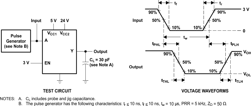
| tPLH | Propagation delay time, low-to-high-level output from A input | L293NE, L293DNE | CL = 30 pF, See Figure 2 |
800 | ns | ||
| L293DWP, L293N L293DN | 750 | ||||||
| tPHL | Propagation delay time, high-to-low-level output from A input | L293NE, L293DNE | 400 | ns | |||
| L293DWP, L293N L293DN | 200 | ||||||
| tTLH | Transition time, low-to-high-level output | L293NE, L293DNE | 300 | ns | |||
| L293DWP, L293N L293DN | 100 | ||||||
| tTHL | Transition time, high-to-low-level output | L293NE, L293DNE | 300 | ns | |||
| L293DWP, L293N L293DN | 350 | ||||||
6.7 Typical Characteristics
 Figure 1. Maximum Power Dissipation vs Ambient Temperature
7 Parameter Measurement Information
 Figure 2. Test Circuit and Voltage Waveforms