-
LM25575 42V、1.5A、降圧型スイッチング・レギュレータ
- 1 特長
- 2 アプリケーション
- 3 概要
- 4 改訂履歴
- 5 Pin Configuration and Functions
- 6 Specifications
- 7 Detailed Description
- 8 Application and Implementation
- 9 Layout
- 10デバイスおよびドキュメントのサポート
- 11メカニカル、パッケージ、および注文情報
- 重要なお知らせ
パッケージ・オプション
メカニカル・データ(パッケージ|ピン)
- PWP|16
サーマルパッド・メカニカル・データ
- PWP|16
発注情報
DATA SHEET
LM25575 42V、1.5A、降圧型スイッチング・レギュレータ
このリソースの元の言語は英語です。 翻訳は概要を便宜的に提供するもので、自動化ツール (機械翻訳) を使用していることがあり、TI では翻訳の正確性および妥当性につきましては一切保証いたしません。 実際の設計などの前には、ti.com で必ず最新の英語版をご参照くださいますようお願いいたします。
1 特長
- 42V、330mΩのNチャネルMOSFETを内蔵
- 非常に広い入力電圧範囲: 6V~42V
- 出力電圧を最低1.225Vまで調整可能
- 1.5%のフィードバック・リファレンス精度
- 単一の抵抗により、動作周波数を50kHz~1MHzの範囲で設定可能
- マスタまたはスレーブの周波数同期
- 調整可能なソフト・スタート
- 電流モード制御アーキテクチャのエミュレーション
- 広帯域幅のエラー・アンプ
- 内蔵の保護機能
- HTSSOP-16EP (露出パッド)
- WEBENCH® Power Designerにより、LM25575を使用するカスタム設計を作成
2 アプリケーション
- 産業用
3 概要
LM25575は、使いやすい降圧型レギュレータで、設計エンジニアは最小点数の部品を使用して、堅牢な電源を設計し、最適化できます。LM25575は6V~42Vの範囲の入力電圧で動作し、内蔵の330mΩ NチャネルMOSFETにより、1.5Aの連続出力電流を供給します。このレギュレータはエミュレーション電流モード・アーキテクチャを活用しているため、ライン・レギュレーション、厳格な負荷過渡応答、容易なループ補償という固有の特性があり、電流モード・レギュレータで一般的な、低いデューティ・サイクルの制限はありません。動作周波数は50kHz~1MHzの範囲に設定でき、サイズと効率を最適化できます。EMIを低減するための周波数同期ピンがあり、LM(2)557xファミリに属する複数のICで、自己同期または外部クロックへの同期を選択できます。LM25575のサイクルごとの電流制限、短絡保護、サーマル・シャットダウン、およびリモート・シャットダウン機能により、堅牢性が保証されます。このデバイスは、放熱を助けるために露出したダイがパッドに取り付けられ、消費可能電力が増大した、HTSSOP-16パッケージで供給されます。LM25575は、 WEBENCH®オンライン設計ツールの完全なスイートでサポートされています。
製品情報(1)
| 型番 | パッケージ | 本体サイズ(公称) |
|---|---|---|
| LM25575 | HTSSOP (16) | 5.00mm×4.40mm |
- 提供されているすべてのパッケージについては、データシートの末尾にある注文情報を参照してください。
簡略化されたアプリケーション回路図

4 改訂履歴
Changes from F Revision (February 2009) to G Revision
- Changed layout of National Data Sheet to TI formatGo
Changes from G Revision (April 2013) to H Revision
- Added 「アプリケーションと実装」セクション、「製品情報」表、「ピン構成および機能」セクション、「ESD定格」表、「熱に関する情報」表、「機能説明」セクション、「デバイスの機能モード」セクション、「デバイスおよびドキュメントのサポート」セクション、「メカニカル、パッケージ、および注文情報」セクションGo
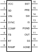
5 Pin Configuration and Functions
PWP
16-Lead HTSSOP
Top View

Pin Functions
| NO. | Name | Description | |
|---|---|---|---|
| 1 | VCC | Output of the bias regulator Vcc tracks Vin up to 9 V. Beyond 9 V, Vcc is regulated to 7 Volts. A 0.1 uF to 1 uF ceramic decoupling capacitor is required. An external voltage (7.5 V – 14 V) can be applied to this pin to reduce internal power dissipation. |
|
| 2 | SD | Shutdown or UVLO input If the SD pin voltage is below 0.7 V the regulator will be in a low power state. If the SD pin voltage is between 0.7 V and 1.225 V the regulator will be in standby mode. If the SD pin voltage is above 1.225 V the regulator will be operational. An external voltage divider can be used to set a line undervoltage shutdown threshold. If the SD pin is left open circuit, a 5 µA pull-up current source configures the regulator fully operational. |
|
| 3 | VIN | Input supply voltage Nominal operating range: 6 V to 42 V |
|
| 4 | SYNC | Oscillator synchronization input or output The internal oscillator can be synchronized to an external clock with an external pull-down device. Multiple LM25575 devices can be synchronized together by connection of their SYNC pins. |
|
| 5 | COMP | Output of the internal error amplifier The loop compensation network should be connected between this pin and the FB pin. |
|
| 6 | FB | Feedback signal from the regulated output This pin is connected to the inverting input of the internal error amplifier. The regulation threshold is 1.225 V. |
|
| 7 | RT | Internal oscillator frequency set input The internal oscillator is set with a single resistor, connected between this pin and the AGND pin. |
|
| 8 | RAMP | Ramp control signal An external capacitor connected between this pin and the AGND pin sets the ramp slope used for current mode control. Recommended capacitor range 50 pF to 2000 pF. |
|
| 9 | AGND | Analog ground Internal reference for the regulator control functions |
|
| 10 | SS | Soft-start An external capacitor and an internal 10 µA current source set the time constant for the rise of the error amp reference. The SS pin is held low during standby, Vcc UVLO and thermal shutdown. |
|
| 11 | OUT | Output voltage connection Connect directly to the regulated output voltage. |
|
| 12 | PGND | Power ground Low side reference for the PRE switch and the IS sense resistor. |
|
| 13 | IS | Current sense Current measurement connection for the re-circulating diode. An internal sense resistor and a sample/hold circuit sense the diode current near the conclusion of the off-time. This current measurement provides the DC level of the emulated current ramp. |
|
| 14 | SW | Switching node The source terminal of the internal buck switch. The SW pin should be connected to the external Schottky diode and to the buck inductor. |
|
| 15 | PRE | Pre-charge assist for the bootstrap capacitor This open drain output can be connected to SW pin to aid charging the bootstrap capacitor during very light load conditions or in applications where the output may be pre-charged before the LM25575 is enabled. An internal pre-charge MOSFET is turned on for 250 ns each cycle just prior to the on-time interval of the buck switch. |
|
| 16 | BST | Boost input for bootstrap capacitor An external capacitor is required between the BST and the SW pins. A 0.022 µF ceramic capacitor is recommended. The capacitor is charged from Vcc via an internal diode during the off-time of the buck switch. |
|
| NA | EP | Exposed Pad Exposed metal pad on the underside of the device. It is recommended to connect this pad to the PWB ground plane, in order to aid in heat dissipation. |
|