JAJSEG0 December   2017 LM25576-Q1

PRODUCTION DATA.  

  1. 特長
  2. アプリケーション
  3. 概要
    1.     Device Images
      1.      簡略化されたアプリケーション回路図
  4. 改訂履歴
  5. Pin Configuration and Functions
    1.     Pin Functions
  6. Specifications
    1. 6.1 Absolute Maximum Ratings
    2. 6.2 ESD Ratings
    3. 6.3 Recommended Operating Conditions
    4. 6.4 Electrical Characteristics
    5. 6.5 Typical Characteristics
  7. Detailed Description
    1. 7.1 Overview
    2. 7.2 Functional Block Diagram
    3. 7.3 Feature Description
      1. 7.3.1 High Voltage Start-Up Regulator
    4. 7.4 Device Functional Modes
      1. 7.4.1 Shutdown and Stand-by Mode
      2. 7.4.2 Oscillator and Sync Capability
      3. 7.4.3 Error Amplifier and PWM Comparator
      4. 7.4.4 RAMP Generator
      5. 7.4.5 Maximum Duty Cycle and Input Drop-Out Voltage
      6. 7.4.6 Current Limit
      7. 7.4.7 Soft-Start
      8. 7.4.8 Boost Pin
      9. 7.4.9 Thermal Protection
  8. Application and Implementation
    1. 8.1 Application Information
      1. 8.1.1  External Components
      2. 8.1.2  R3 (RT)
      3. 8.1.3  L1
      4. 8.1.4  C3 (CRAMP)
      5. 8.1.5  C9, C10
      6. 8.1.6  D1
      7. 8.1.7  C1, C2
      8. 8.1.8  C8
      9. 8.1.9  C7
      10. 8.1.10 C4
      11. 8.1.11 R5, R6
      12. 8.1.12 R1, R2, C12
      13. 8.1.13 R7, C11
      14. 8.1.14 R4, C5, C6
      15. 8.1.15 Bias Power Dissipation Reduction
    2. 8.2 Typical Application
      1. 8.2.1 Typical Schematic for High Frequency (1 MHz) Application
      2. 8.2.2 Typical Schematic for Buck and Boost (Inverting) Application
  9. Layout
    1. 9.1 Layout Guidelines
      1. 9.1.1 PCB Layout and Thermal Considerations
    2. 9.2 Layout Example
  10. 10デバイスおよびドキュメントのサポート
    1. 10.1 デバイス・サポート
      1. 10.1.1 開発サポート
        1. 10.1.1.1 WEBENCH®ツールによるカスタム設計
    2. 10.2 ドキュメントの更新通知を受け取る方法
    3. 10.3 コミュニティ・リソース
    4. 10.4 商標
    5. 10.5 静電気放電に関する注意事項
    6. 10.6 Glossary
  11. 11メカニカル、パッケージ、および注文情報

パッケージ・オプション

メカニカル・データ(パッケージ|ピン)
サーマルパッド・メカニカル・データ
発注情報

L1

The inductor value is determined based on the operating frequency, load current, ripple current, and the minimum and maximum input voltage (VIN(min), VIN(max)).
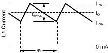
LM25576-Q1 20208710.gifFigure 14. Inductor Current Waveform

To keep the circuit in continuous conduction mode (CCM), the maximum ripple current IRIPPLE should be less than twice the minimum load current, or 0.5 Ap-p. Using this value of ripple current, the value of inductor (L1) is calculated using the following:

Equation 6. LM25576-Q1 20208711.gif
Equation 7. LM25576-Q1 20208712.gif

This procedure provides a guide to select the value of L1. The nearest standard value (33 µH) will be used. L1 must be rated for the peak current (IPK+) to prevent saturation. During normal loading conditions, the peak current occurs at maximum load current plus maximum ripple. During an overload condition the peak current is limited to 4.2 A nominal (5.1 A maximum). The selected inductor (see Table 1) has a conservative 6.2 Amp saturation current rating. For this manufacturer, the saturation rating is defined as the current necessary for the inductance to reduce by 30%, at 20°C.