-
LM2599 SIMPLE SWITCHER®電力コンバータ、150kHz 3A降圧型電圧レギュレータ(追加機能付き)
- 1 特長
- 2 アプリケーション
- 3 概要
- 4 改訂履歴
- 5 概要(続き)
- 6 Pin Configuration and Functions
-
7 Specifications
- 7.1 Absolute Maximum Ratings
- 7.2 ESD Ratings
- 7.3 Recommended Operating Conditions
- 7.4 Thermal Information
- 7.5 Electrical Characteristics - 3.3-V Version
- 7.6 Electrical Characteristics - 5-V Version
- 7.7 Electrical Characteristics - 12-V Version
- 7.8 Electrical Characteristics - Adjustable Voltage Version
- 7.9 Electrical Characteristics - All Output Voltage Versions
- 7.10 Typical Characteristics
- 8 Detailed Description
-
9 Application and Implementation
- 9.1
Application Information
- 9.1.1 Soft-Start Capacitor (CSS)
- 9.1.2 Delay Capacitor (CDELAY)
- 9.1.3 Feedforward Capacitor (CFF) for Adjustable Output Voltage Version Only
- 9.1.4 Input Capacitor (CIN)
- 9.1.5 Output Capacitor (COUT)
- 9.1.6 Catch Diode
- 9.1.7 Inductor Selection
- 9.1.8 Output Voltage Ripple and Transients
- 9.1.9 Open Core Inductors
- 9.2 Typical Applications
- 9.1
Application Information
- 10Power Supply Recommendations
- 11Layout
- 12デバイスおよびドキュメントのサポート
- 13メカニカル、パッケージ、および注文情報
- 重要なお知らせ
パッケージ・オプション
メカニカル・データ(パッケージ|ピン)
サーマルパッド・メカニカル・データ
- KTW|7
発注情報
LM2599 SIMPLE SWITCHER®電力コンバータ、150kHz 3A降圧型電圧レギュレータ(追加機能付き)
1 特長
2 アプリケーション
- シンプルな高効率降圧型(バック)レギュレータ
- リニア・レギュレータ用の高効率プリレギュレータ
- オンボード・スイッチング・レギュレータ
- 反転型コンバータ
3 概要
LM2599シリーズのレギュレータは、降圧型(バック)スイッチング・レギュレータのすべてのアクティブ機能を内蔵したモノリシックICで、優れたラインおよび負荷レギュレーションで 3Aの負荷を駆動できます。これらのデバイスは、3.3V、5V、12Vの固定出力電圧と、可変出力バージョンで利用可能です。
LM2598はLM259xファミリのメンバーで、監視およびパフォーマンスの機能が追加されています。
必要な外付け部品が少なくてすみ、使い方が簡単で、内部周波数補償、ラインおよび負荷の仕様の強化、固定周波数のオシレータ、シャットダウン/ソフトスタート、エラー・フラグ遅延、およびエラー・フラグ出力の機能を備えています。
製品情報(1)
| 型番 | パッケージ | 本体サイズ(公称) |
|---|---|---|
| LM2599 | TO-220 (7) | 14.986mm×10.16mm |
| TO-263 (7) | 10.10mm×8.89mm |
- 提供されているすべてのパッケージについては、巻末の注文情報を参照してください。
代表的なアプリケーション

4 改訂履歴
Changes from C Revision (April 2013) to D Revision
- 「ESD定格」の表、「機能説明」セクション、「デバイスの機能モード」セクション、「アプリケーションと実装」セクション、「電源に関する推奨事項」セクション、「レイアウト」セクション、「デバイスおよびドキュメントのサポート」セクション、「メカニカル、パッケージ、および注文情報」セクションを追加Go
- デザイン・ソフトウェアSwitchers Made Simpleへの言及をすべて削除Go
Changes from B Revision (April 2013) to C Revision
- Changed layout of National Semiconductor Data Sheet to TI formatGo
5 概要(続き)
LM2599シリーズは150kHzのスイッチング周波数で動作するため、低周波数で動作するスイッチング・レギュレータに比べて、サイズの小さなフィルタ部品を使用できます。標準的な7ピンのTO-220パッケージで、いくつかの異なるリードフォーミング品で供給されるほか、7ピンのTO-263表面実装パッケージでも供給されます。
LM2599シリーズでの使用に最適な標準インダクタ(スルーホールと表面実装タイプのいずれも)をいくつかのメーカーから入手できます。このため、スイッチング電源の設計が大幅に簡素化されます。
また、入力電圧と出力負荷のあらゆる条件において、出力電圧について±4%、オシレータ周波数について±15%の許容誤差が保証されています。外部シャットダウンが搭載されており、スタンバイ電流は標準値で80μAです。自己保護機能として、出力スイッチのための2段階電流制限回路と、異常時でも完全に保護動作が保証される過熱シャットダウン機能を備えています。
6 Pin Configuration and Functions
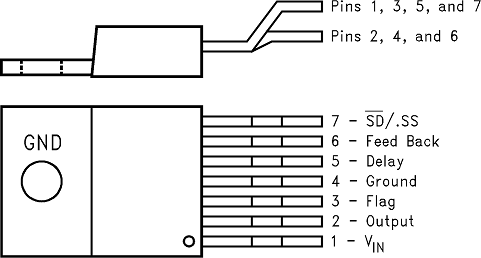
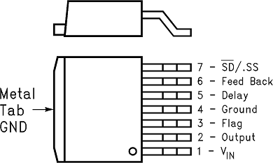
Pin Functions(1)
| PIN | I/O | DESCRIPTION | |
|---|---|---|---|
| NO. | NAME | ||
| 1 | +VIN | I | This is the positive input supply for the IC switching regulator. A suitable input bypass capacitor must be present at this pin to minimize voltage transients and to supply the switching currents needed by the regulator. |
| 2 | Output | O | Internal switch. The voltage at this pin switches between approximately (+VIN − VSAT) and approximately −0.5 V, with a duty cycle of VOUT/VIN. To minimize coupling to sensitive circuitry, the PCB copper area connected to this pin must be kept to a minimum. |
| 3 | Error Flag | O | Open-collector output that provides a low signal (flag transistor ON) when the regulated output voltage drops more than 5% from the nominal output voltage. On start up, Error Flag is low until VOUT reaches 95% of the nominal output voltage and a delay time determined by the Delay pin capacitor. This signal can be used as a reset to a microprocessor on power-up. |
| 4 | Ground | — | Circuit ground. |
| 5 | Delay | O | At power-up, this pin can be used to provide a time delay between the time the regulated output voltage reaches 95% of the nominal output voltage, and the time the error flag output goes high. |
| 6 | Feedback | I | Senses the regulated output voltage to complete the feedback loop. |
| 7 | Shutdown/Soft-start | I | This dual function pin provides the following features: (a) Allows the switching regulator circuit to be shut down using logic level signals thus dropping the total input supply current to approximately 80 μA. (b) Adding a capacitor to this pin provides a soft-start feature which minimizes start-up current and provides a controlled ramp up of the output voltage. |
7 Specifications
7.1 Absolute Maximum Ratings (1)(2)
| MIN | MAX | UNIT | |||
|---|---|---|---|---|---|
| Maximum supply voltage, VIN | 45 | V | |||
| SD/SS pin input voltage(3) | 6 | V | |||
| Delay pin voltage(3) | 1.5 | V | |||
| Flag pin voltage | –0.3 | 45 | V | ||
| Feedback pin voltage | –0.3 | 25 | V | ||
| Output voltage to ground (steady-state) | –1 | V | |||
| Power dissipation | Internally limited | ||||
| Lead temperature | KTW package | Vapor phase (60 s) | 215 | °C | |
| Infrared (10 s) | 245 | ||||
| NDZ package (soldering, 10 s) | 260 | ||||
| Maximum junction temperature | 150 | °C | |||
| Storage temperature, Tstg | −65 | 150 | °C | ||
7.2 ESD Ratings
| VALUE | UNIT | |||
|---|---|---|---|---|
| V(ESD) | Electrostatic discharge | Human-body model (HBM), per ANSI/ESDA/JEDEC JS-001(1) | ±2000 | V |
7.3 Recommended Operating Conditions
| MIN | MAX | UNIT | |
|---|---|---|---|
| Supply voltage | 4.5 | 40 | V |
| Temperature | –40 | 125 | °C |
7.4 Thermal Information
| THERMAL METRIC(1) | LM2599 | UNIT | |||
|---|---|---|---|---|---|
| KTW (TO-263) | NDZ (TO-220) | ||||
| 7 PINS | 7 PINS | ||||
| RθJA | Junction-to-ambient thermal resistance(2)(3) | See(4) | — | 50 | °C/W |
| See(5) | 50 | — | |||
| See(6) | 30 | — | |||
| See(7) | 20 | — | |||
| RθJC(top) | Junction-to-case (top) thermal resistance | 2 | 2 | °C/W | |
7.5 Electrical Characteristics – 3.3-V Version
Specifications are for TJ = 25°C (unless otherwise noted).| PARAMETER | TEST CONDITIONS | MIN(1) | TYP(2) | MAX (1) | UNIT | ||
|---|---|---|---|---|---|---|---|
| SYSTEM PARAMETERS(3) (see Figure 43 for test circuit) | |||||||
| VOUT | Output voltage | 4.75 V ≤ VIN ≤ 40 V, 0.2 A ≤ ILOAD ≤ 3 A |
TJ = 25°C | 3.168 | 3.3 | 3.432 | V |
| –40°C ≤ TJ ≤ 125°C | 3.135 | 3.465 | |||||
| η | Efficiency | VIN = 12 V, ILOAD = 3 A | 73% | ||||
7.6 Electrical Characteristics – 5-V Version
Specifications are for TJ = 25°C (unless otherwise noted).| PARAMETER | TEST CONDITIONS | MIN(1) | TYP(2) | MAX(1) | UNIT | ||
|---|---|---|---|---|---|---|---|
| SYSTEM PARAMETERS(3) (see Figure 43 for test circuit) | |||||||
| VOUT | Output voltage | 7 V ≤ VIN ≤ 40 V, 0.2 A ≤ ILOAD ≤ 3 A |
TJ = 25°C | 4.8 | 5 | 5.2 | V |
| –40°C ≤ TJ ≤ 125°C | 4.75 | 5.25 | |||||
| η | Efficiency | VIN = 12 V, ILOAD = 3 A | 80% | ||||
7.7 Electrical Characteristics – 12-V Version
Specifications are for TJ = 25°C (unless otherwise noted).| PARAMETER | TEST CONDITIONS | MIN(1) | TYP(2) | MAX(1) | UNIT | ||
|---|---|---|---|---|---|---|---|
| SYSTEM PARAMETERS(3) (see Figure 43 for test circuit) | |||||||
| VOUT | Output voltage | 15 V ≤ VIN ≤ 40 V, 0.2 A ≤ ILOAD ≤ 3 A |
TJ = 25°C | 11.52 | 12 | 12.48 | V |
| –40°C ≤ TJ ≤ 125°C | 11.4 | 12.6 | |||||
| η | Efficiency | VIN = 25 V, ILOAD = 3 A | 90% | ||||
7.8 Electrical Characteristics – Adjustable Voltage Version
Specifications are for TJ = 25°C (unless otherwise noted).| PARAMETER | TEST CONDITIONS | MIN(1) | TYP(2) | MAX(1) | UNIT | ||
|---|---|---|---|---|---|---|---|
| SYSTEM PARAMETERS(3) (see Figure 43 for test circuit) | |||||||
| VFB | Feedback voltage | 4.5 V ≤ VIN ≤ 40 V, 0.2 A ≤ ILOAD ≤ 3 A | 1.23 | V | |||
| VOUT programmed for 3 V, circuit of Figure 43 |
TJ = 25°C | 1.193 | 1.267 | ||||
| –40°C ≤ TJ ≤ 125°C | 1.18 | 1.28 | |||||
| η | Efficiency | VIN = 12 V, VOUT = 3 V, ILOAD = 3 A | 73% | ||||
7.9 Electrical Characteristics – All Output Voltage Versions
Specifications are for TJ = 25°C, ILOAD = 500 mA, VIN = 12 V for the 3.3-V, 5-V, and Adjustable version, and VIN = 24 V for the 12-V version (unless otherwise noted).| PARAMETER | TEST CONDITIONS | MIN(1) | TYP(2) | MAX(1) | UNIT | ||
|---|---|---|---|---|---|---|---|
| DEVICE PARAMETERS | |||||||
| Ib | Feedback bias current | Adjustable voltage version only, VFB = 1.3 V | TJ = 25°C | 10 | 50 | nA | |
| –40°C ≤ TJ ≤ 125°C | 100 | ||||||
| fO | Oscillator frequency(3) | TJ = 25°C | 127 | 150 | 173 | kHz | |
| –40°C ≤ TJ ≤ 125°C | 110 | 173 | |||||
| VSAT | Saturation voltage | IOUT = 3 A(4)(5) | TJ = 25°C | 1.16 | 1.4 | V | |
| –40°C ≤ TJ ≤ 125°C | 1.5 | ||||||
| DC | Max duty cycle (ON)(5) | 100% | |||||
| Min duty cycle (OFF)(6) | 0% | ||||||
| ICL | Current limit | Peak current(4) (5) | TJ = 25°C | 3.6 | 4.5 | 6.9 | A |
| –40°C ≤ TJ ≤ 125°C | |||||||
| 3.4 | 7.5 | ||||||
| IL | Output leakage current | Output = 0 V, VIN = 40 V(4) (6) | 50 | μA | |||
| Output = −1 V | 2 | 30 | mA | ||||
| IQ | Operating quiescent current | SD/SS pin open(6) | 5 | 10 | mA | ||
| ISTBY | Current standby quiescent | SD/SS pin = 0 V, VIN = 40 V | TJ = 25°C | 80 | 200 | μA | |
| –40°C ≤ TJ ≤ 125°C | 250 | μA | |||||
| SHUTDOWN/SOFT-START CONTROL – See Figure 43 | |||||||
| VSD | Shutdown threshold voltage | 1.3 | V | ||||
| Low (Shutdown mode), –40°C ≤ TJ ≤ 125°C | 0.6 | ||||||
| High (Soft-start mode), –40°C ≤ TJ ≤ 125°C | 2 | ||||||
| VSS | Soft-start voltage | VOUT = 20% of nominal output voltage | 2 | V | |||
| VOUT = 100% of nominal output voltage | 3 | ||||||
| ISD | Shutdown current | VSHUTDOWN = 0.5 V | 5 | 10 | μA | ||
| ISS | Soft-start current | VSoft-start = 2.5 V | 1.6 | 5 | μA | ||
| FLAG/DELAY CONTROL – See Figure 43 | |||||||
| Regulator dropout detector threshold voltage | Low (flag ON) | 92% | 96% | 98% | |||
| VFSAT | Voltage flag output saturation | ISINK = 3 mA | 0.3 | V | |||
| VDELAY = 0.5 V | TJ = 25°C | 0.7 | V | ||||
| –40°C ≤ TJ ≤ 125°C | 1 | ||||||
| IFL | Flag output leakage current | VFLAG = 40 V | 0.3 | μA | |||
| Voltage delay pin threshold | 1.25 | V | |||||
| Low (flag ON) | 1.21 | V | |||||
| High (flag OFF) and VOUT regulated | 1.29 | ||||||
| Delay pin source current | VDELAY = 0.5 V | 3 | 6 | μA | |||
| Delay pin saturation | Low (flag ON) | TJ = 25°C | 55 | 350 | mV | ||
| –40°C ≤ TJ ≤ 125°C | 400 | ||||||
7.10 Typical Characteristics
See Figure 43 for test circuit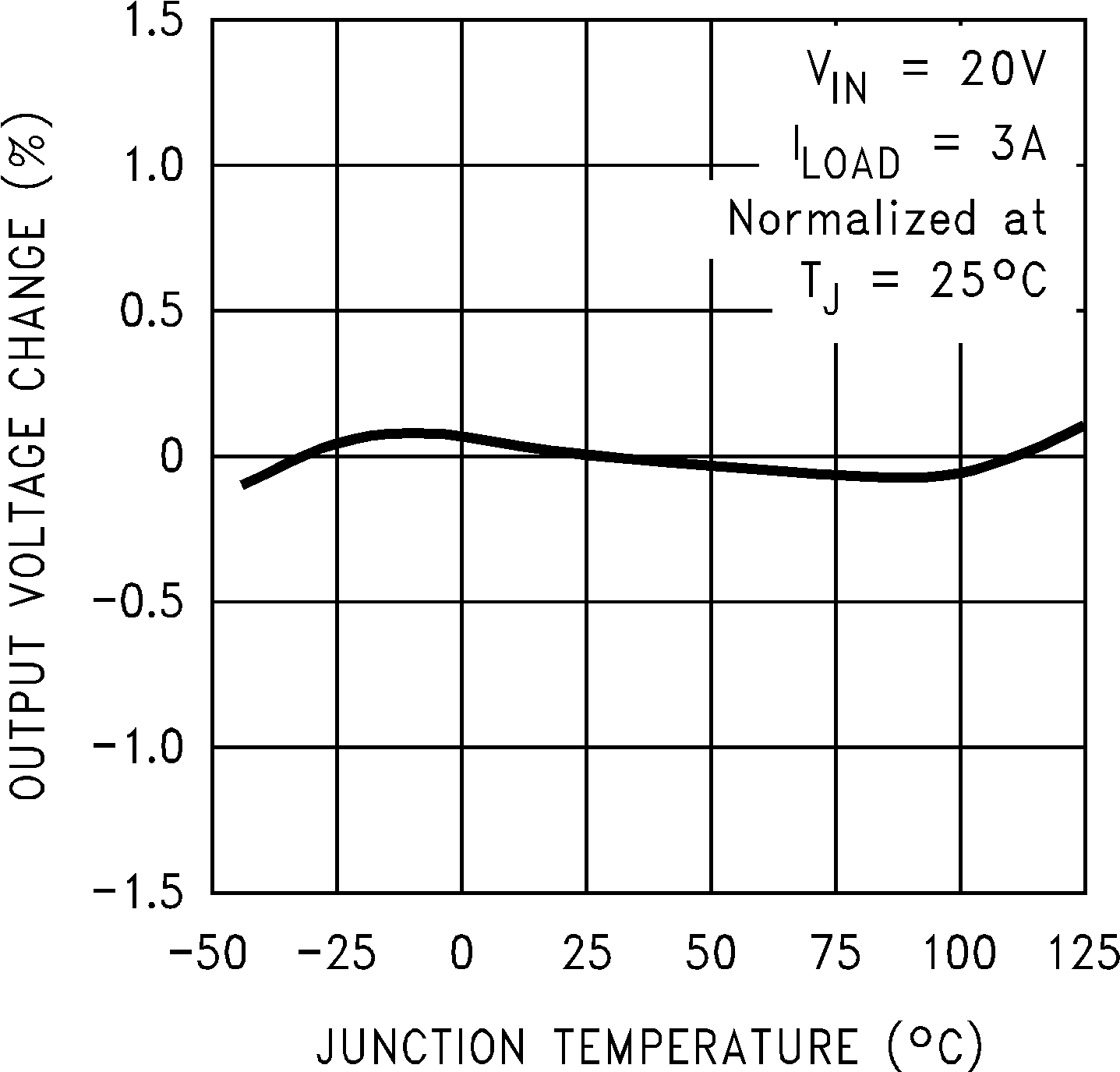 Figure 1. Normalized Output Voltage
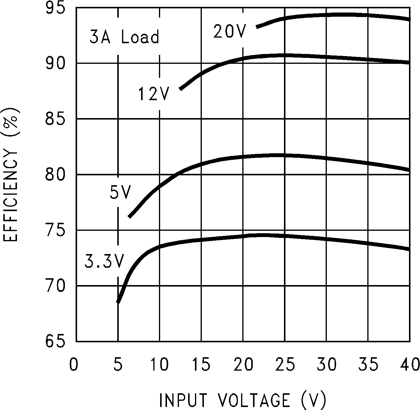 Figure 3. Efficiency
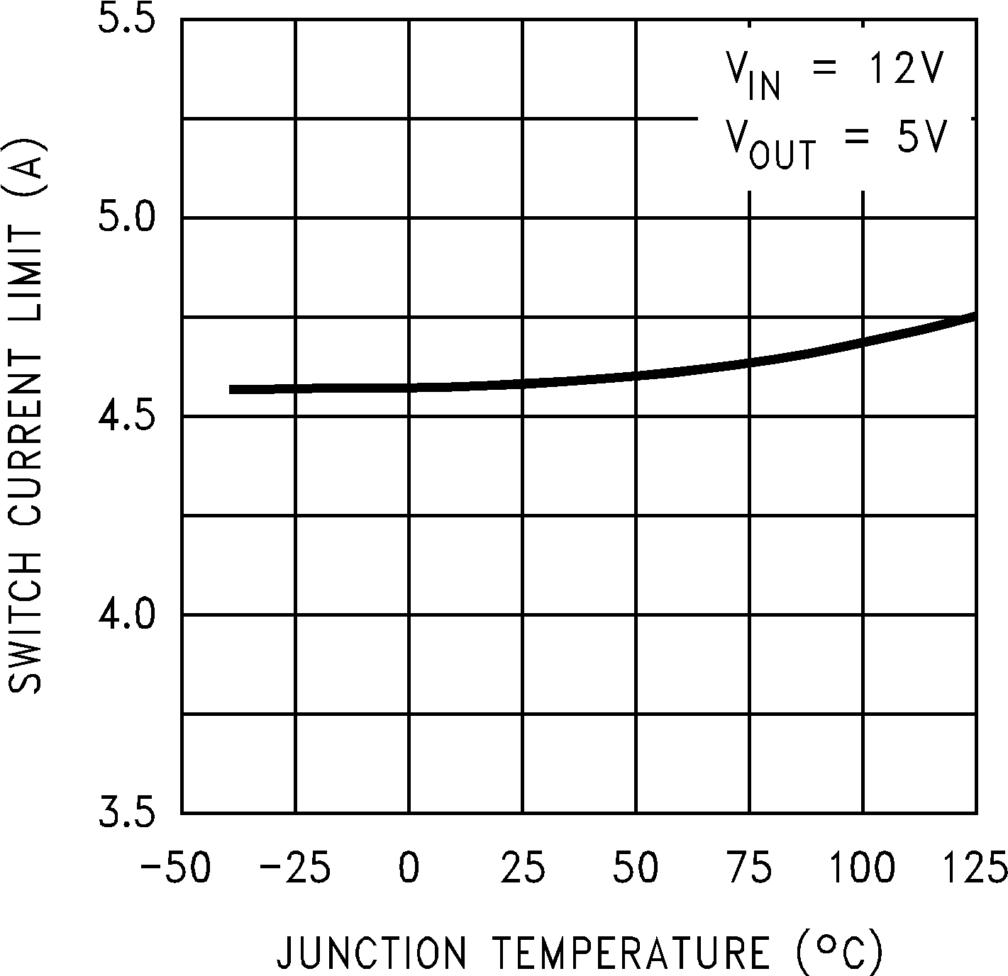 Figure 5. Switch Current Limit
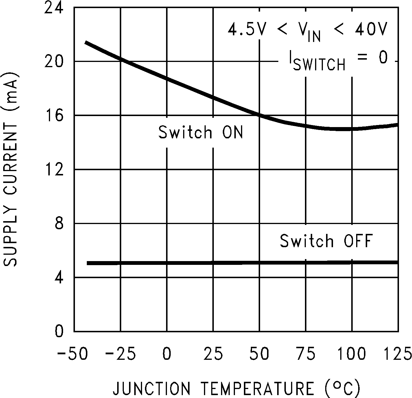 Figure 7. Operating Quiescent Current
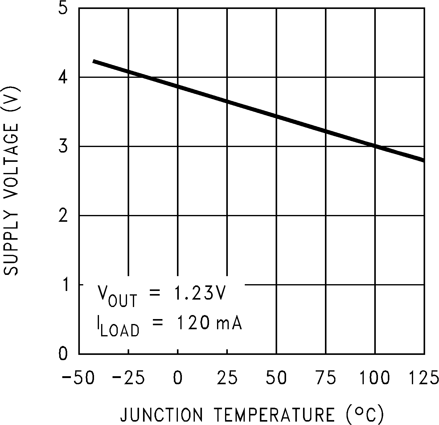 Figure 9. Minimum Operating Supply Voltage
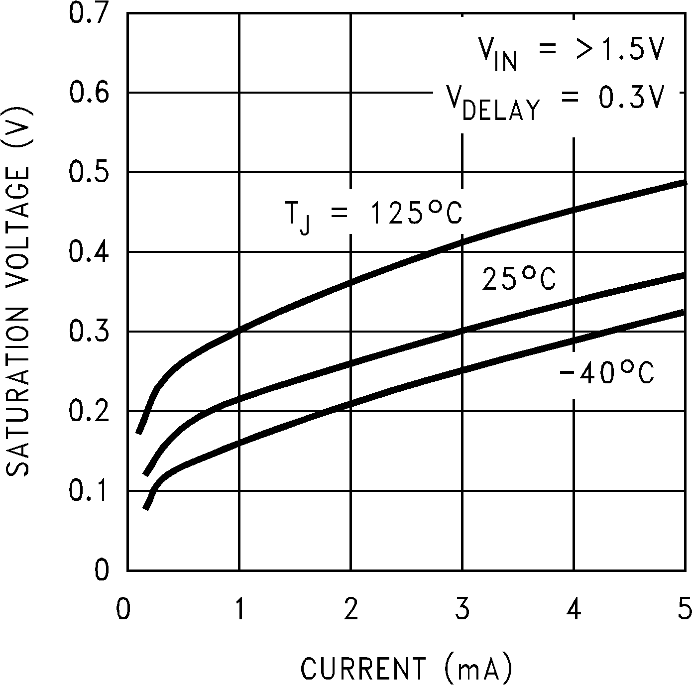 Figure 11. Flag Saturation Voltage
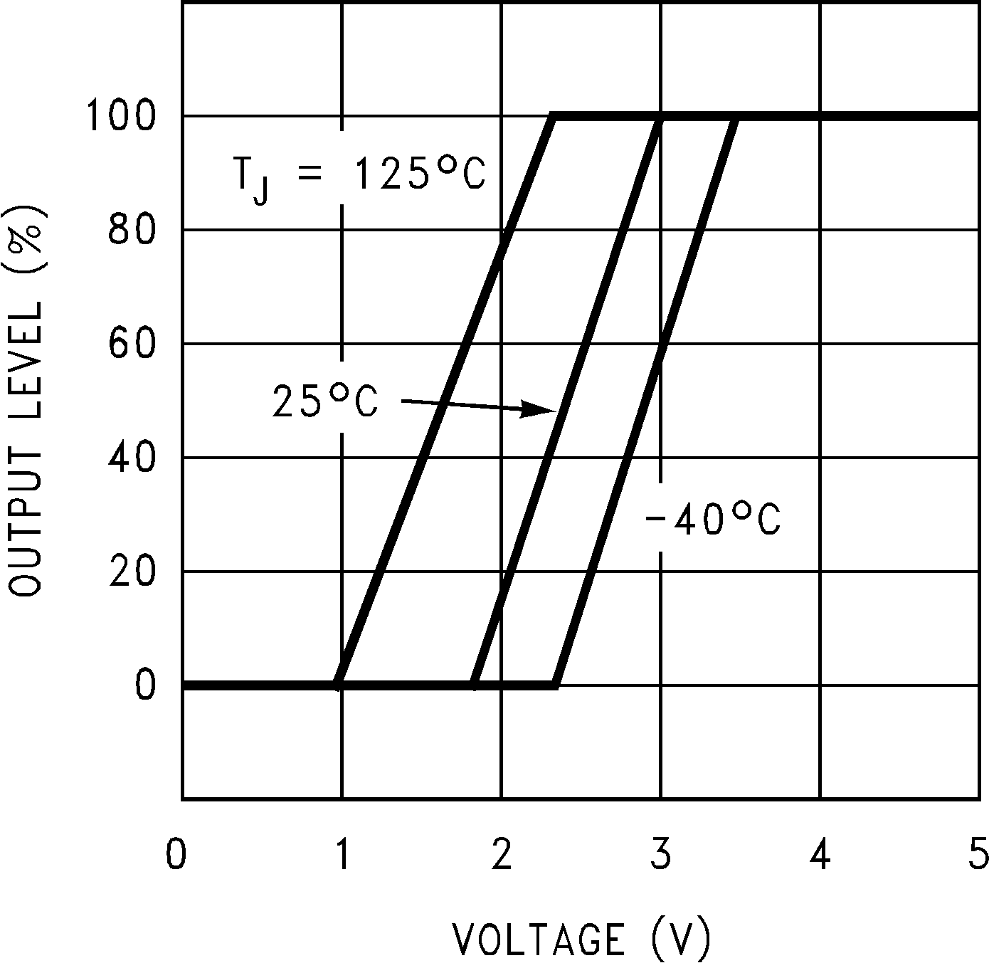 Figure 13. Soft-Start
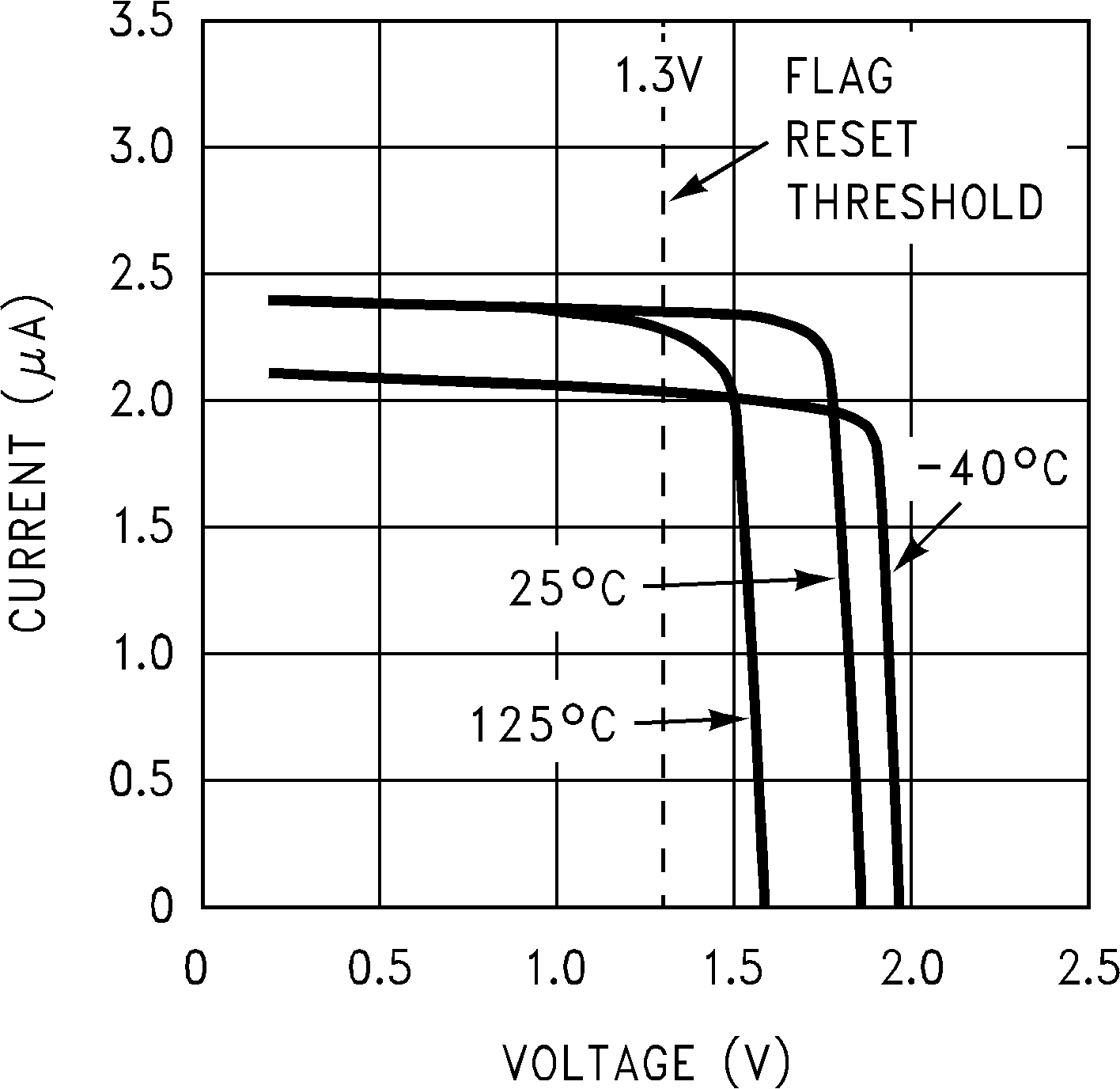 Figure 15. Daisy Pin Current
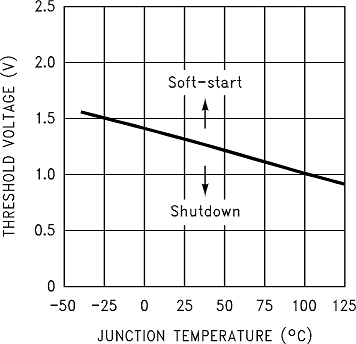 Figure 17. Shutdown/Soft-Start Threshold Voltage
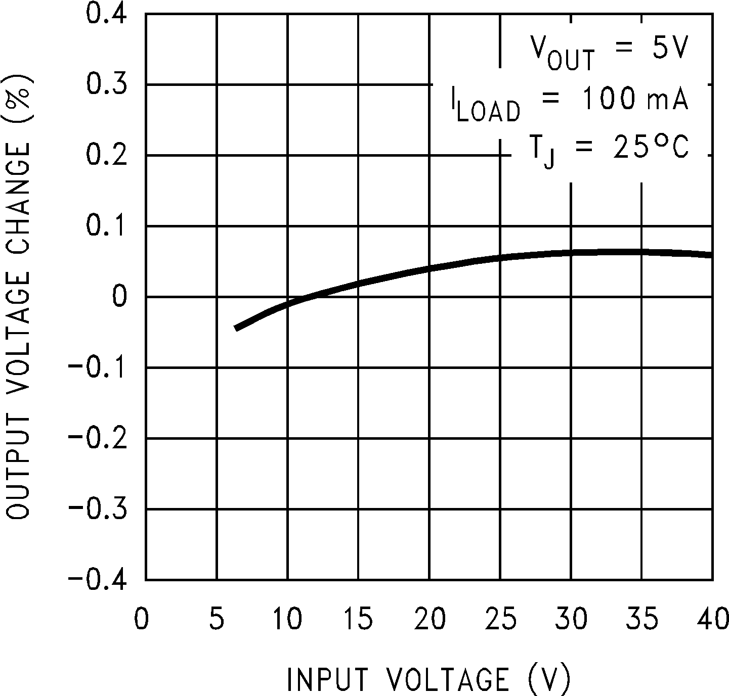 Figure 2. Line Regulation
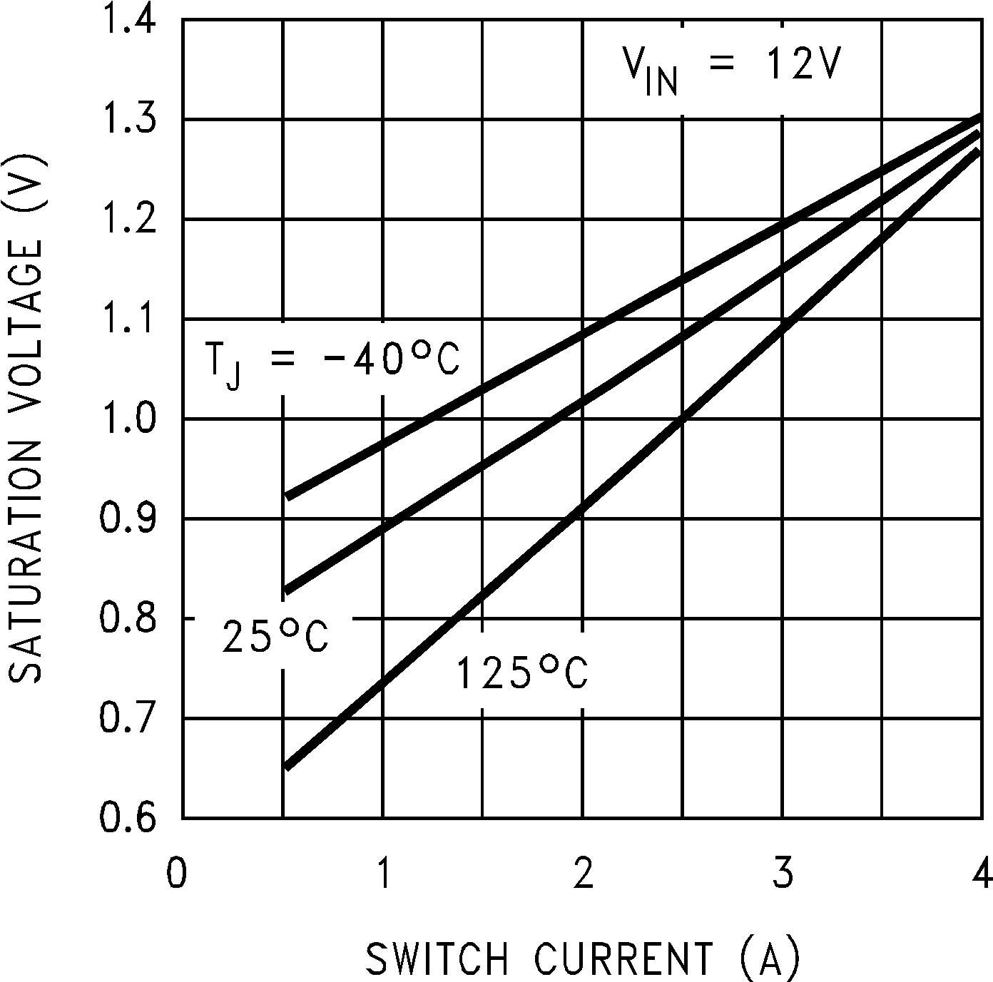 Figure 4. Switch Saturation Voltage
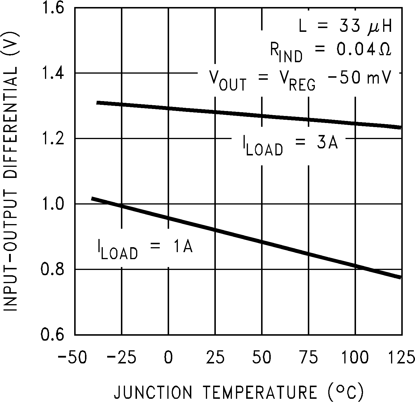 Figure 6. Dropout Voltage
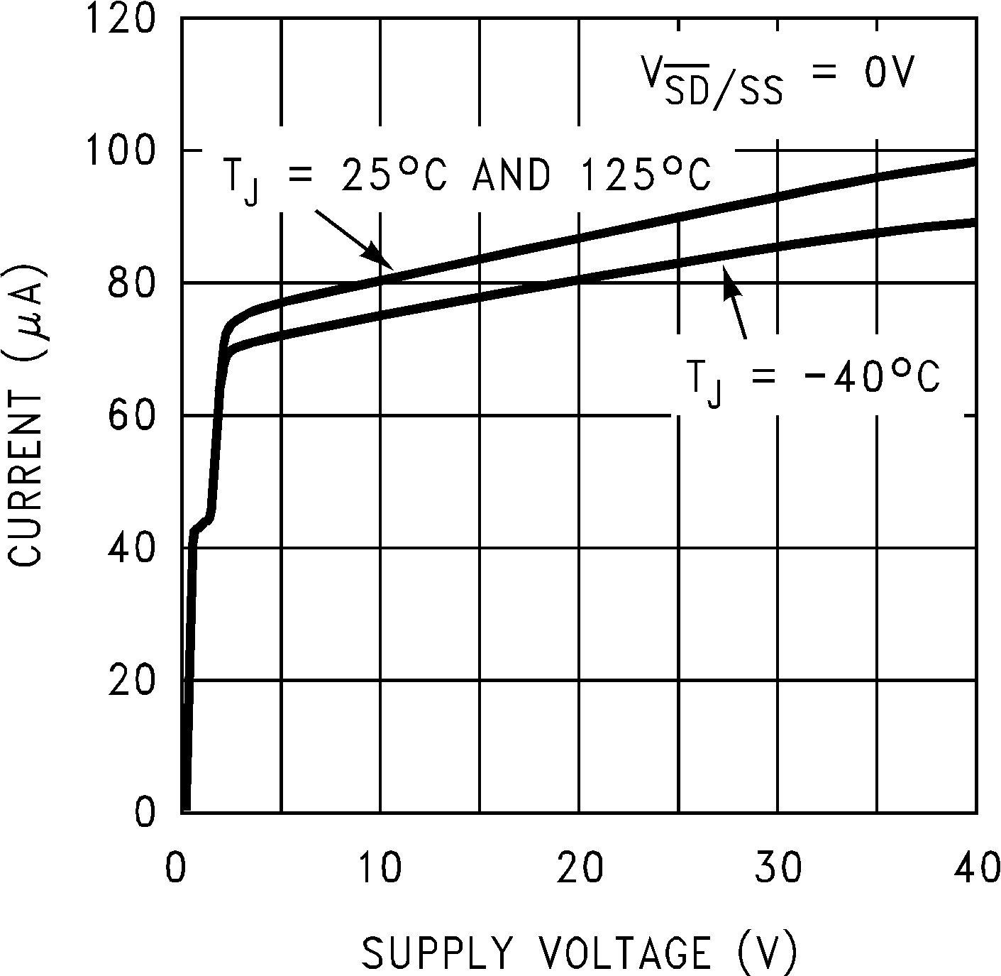 Figure 8. Shutdown Quiescent Current
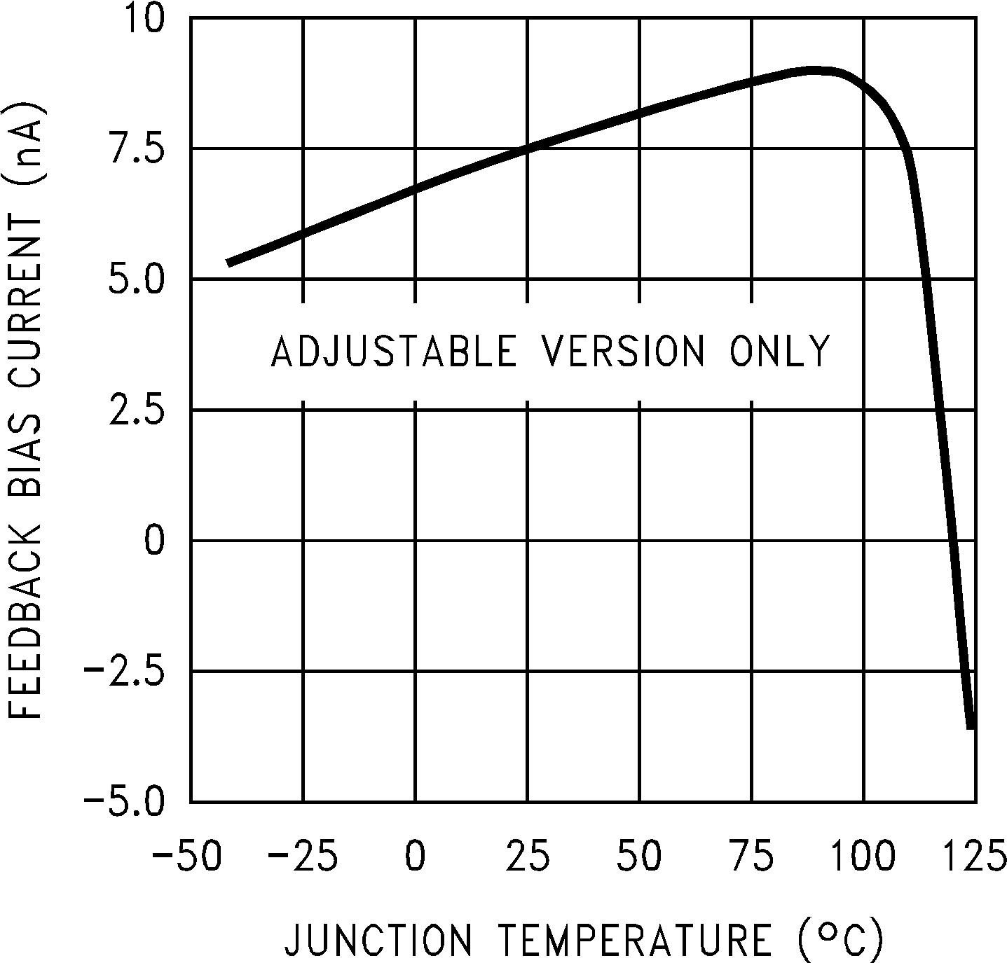 Figure 10. Feedback Pin Bias Current
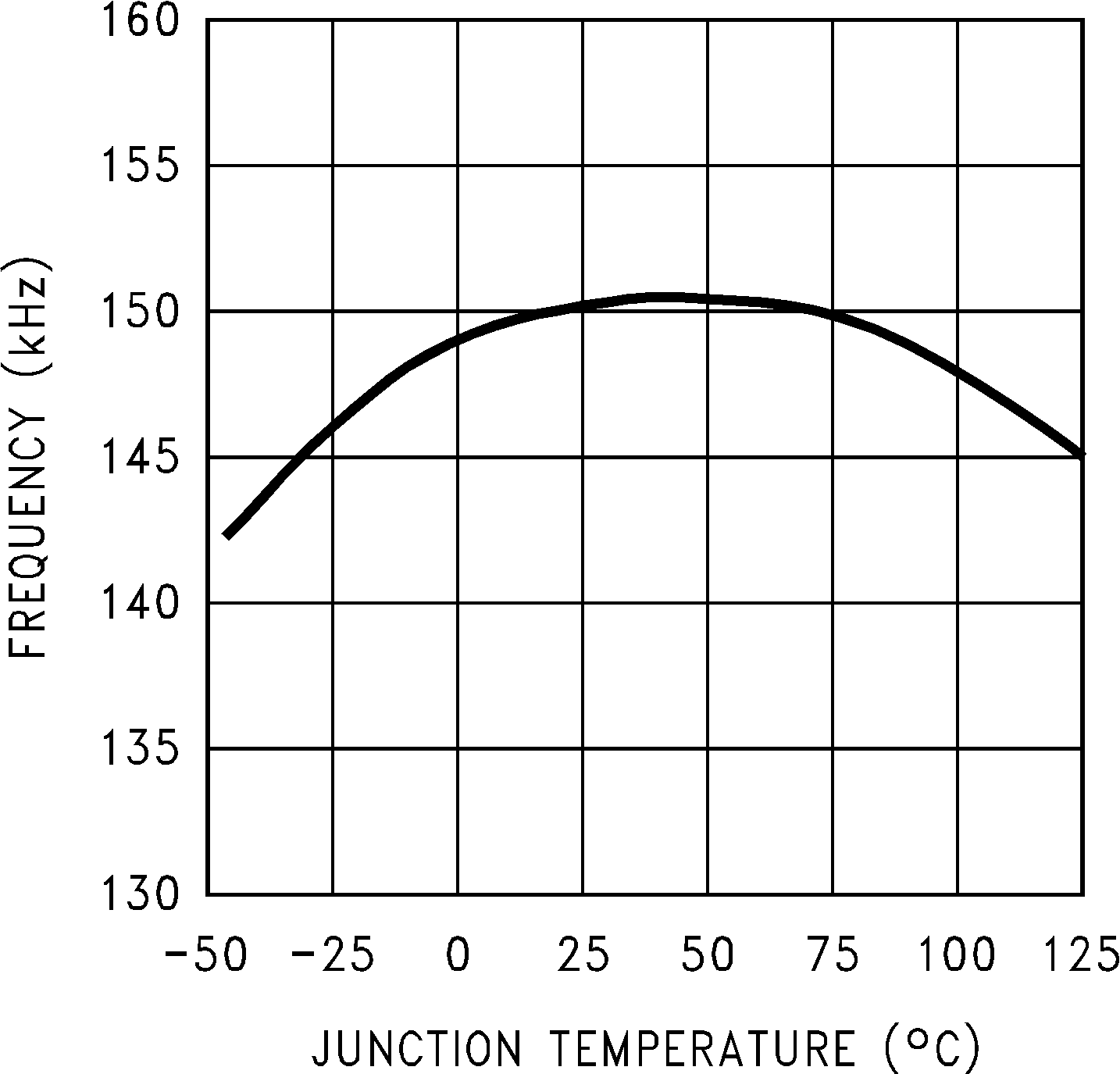 Figure 12. Switching Frequency
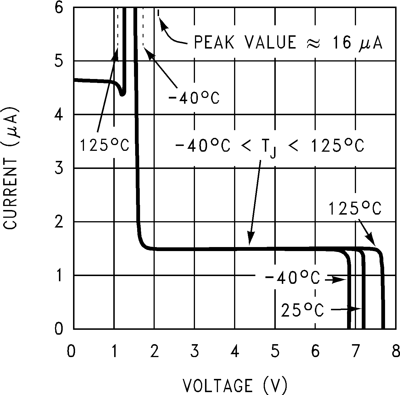 Figure 14. Shutdown/Soft-Start Current
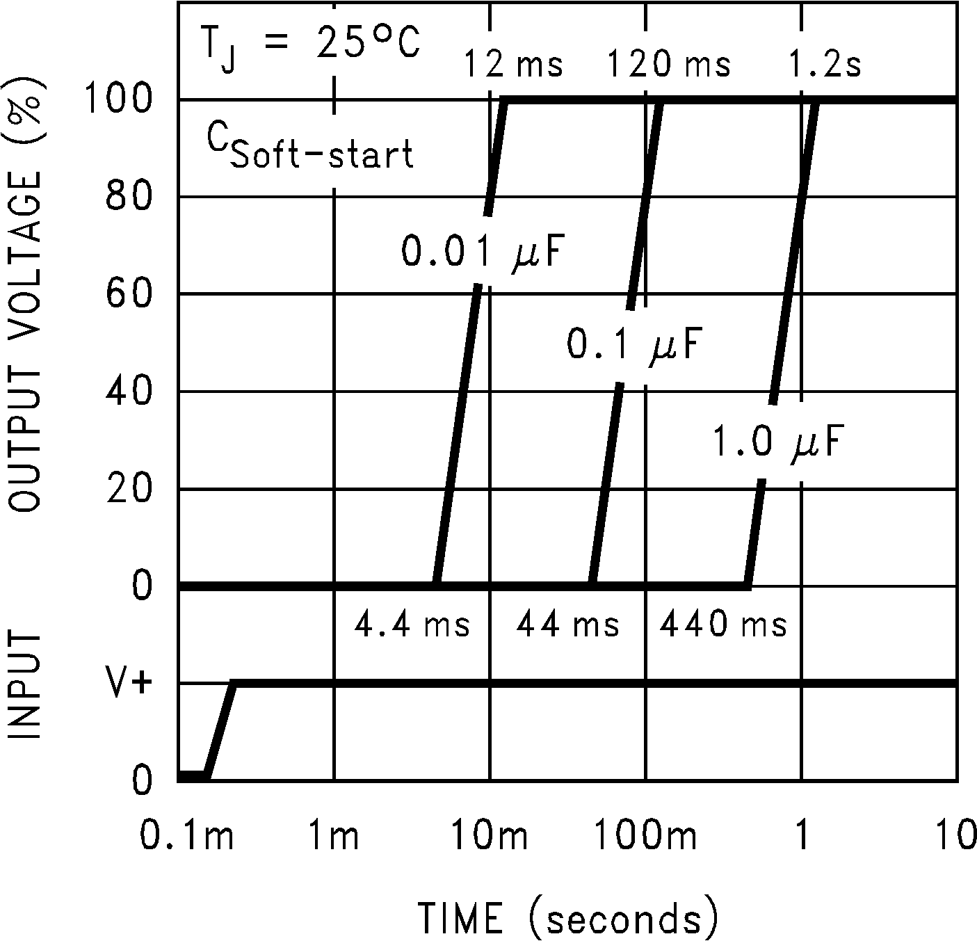 Figure 16. Soft-Start Response