-
LM3017 High Efficiency Low-Side Controller With True Shutdown
- 1 Features
- 2 Applications
- 3 Description
- 4 Revision History
- 5 Pin Configuration and Functions
- 6 Specifications
- 7 Detailed Description
-
8 Application and Implementation
- 8.1 Application Information
- 8.2
Typical Application
- 8.2.1 Design Requirements
- 8.2.2
Detailed Design Procedure
- 8.2.2.1 Programming the Output Voltage
- 8.2.2.2 Power Inductor Selection
- 8.2.2.3 Setting the Output Current
- 8.2.2.4 Additional Slope Compensation
- 8.2.2.5 Current Limit With Additional Slope Compensation
- 8.2.2.6 Power Diode Selection
- 8.2.2.7 Low-Side MOSFET Selection (Switching MOSFET)
- 8.2.2.8 Pass MOSFET Selection (High-Side MOSFET)
- 8.2.2.9 Input Capacitor Selection
- 8.2.2.10 Output Capacitor Selection
- 8.2.2.11 VCC Decoupling Capacitor
- 8.2.2.12 Slope Compensation Ramp
- 8.2.2.13 Control Loop Compensation
- 8.2.3 Application Curve
- 9 Power Supply Recommendations
- 10Layout
- 11Device and Documentation Support
- 12Mechanical, Packaging, and Orderable Information
- IMPORTANT NOTICE
LM3017 High Efficiency Low-Side Controller With True Shutdown
1 Features
- Fully Compliant to Thunderbolt™ Technology Specifications
- True Shutdown for Short-Circuit Protection
- Input Side Current Limit
- Single Enable Pin With Three Modes of Operation: Boost, Pass-Through, or Shutdown
- Built-in Charge Pump for High-Side NFET Disconnect Switch
- 1-A Push-Pull Driver for Low-Side NFET
- Peak Current Mode Control
- Simple Slope Compensation
- Protection Features: Thermal Shutdown, Cycle-by-Cycle Current Limit, Short-Circuit Protection, Output Overvoltage Protection, and Latch-Off
- Internal Soft Start
- Input Voltage Range: 5 V to 18 V
- 600-kHz Fixed Frequency Operation
- ±1% Reference Voltage Accuracy Over Temperature
- Low Shutdown Current (< 1 µA), 40 nA Typical
- 2.4 mm × 2.7 mm × 0.8 mm, 10-Pin WQFN Package
2 Applications
- Thunderbolt™ Technology Host Ports
- Notebook and Desktop Computers, Tablets, and Other Portable Consumer Electronics
- Hard Disc Drives, Solid-State Drives
- Offline Power Supplies
- Set-Top Boxes
3 Description
The LM3017 device is a versatile low-side NFET controller incorporating true shutdown and input side current limiting. The LM3017 is designed for simple implementation of boost conversions in Thunderbolt™ Technology. The LM3017 can also be configured for flyback or SEPIC designs. The input voltage range of 5 V to 18 V accommodates a two- or three-cell lithium ion battery or a 12-V rail. The enable pin accepts a single input to drive three different modes of operation: boost, pass-through, or shutdown mode. The LM3017 draws very low current in shutdown mode, typically 40 nA from the input supply.
The LM3017 provides an adjustable output to drive the Power Load Switch or MUX for the host Thunderbolt™ port. The ability to drive an external high-side NMOS provides for true isolation of the load from the input. Current limiting on the input ensures that inrush and short-circuit currents are always under control. The LM3017 incorporates built-in thermal shutdown, cycle-by-cycle current limit, short-circuit protection, output overvoltage protection, and soft start. It is available in a 10-pin WQFN package.
Device Information(1)
| PART NUMBER | PACKAGE | BODY SIZE (NOM) |
|---|---|---|
| LM3017 | WQFN (10) | 2.40 mm × 2.70 mm |
- For all available packages, see the orderable addendum at the end of the data sheet.
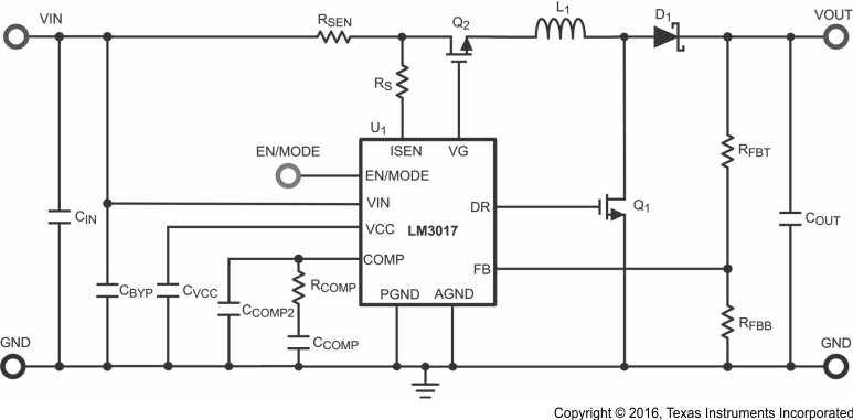
Typical Application Circuit

4 Revision History
Changes from C Revision (March 2013) to D Revision
- Added ESD Ratings table, Feature Description section, Device Functional Modes, Application and Implementation section, Power Supply Recommendations section, Layout section, Device and Documentation Support section, and Mechanical, Packaging, and Orderable Information sectionGo
- Changed RθJA value in the Thermal Information table From: 36 To: 79.2Go
Changes from B Revision (November 2012) to C Revision
- Added Updated to Rev C as Rev A and B were SVA ConfidentialsGo
5 Pin Configuration and Functions

Pin Functions
| PIN | TYPE(1) | DESCRIPTION | ||
|---|---|---|---|---|
| NO. | NAME | |||
| 1 | VCC | O | Driver supply voltage pin: output of internal regulator powering low side NMOS driver. A minimum of 0.47 µF must be connected from this pin to PGND for proper operation. | |
| 2 | DR | O | Low-side NMOS gate driver output: output gate drive to low side NMOS gate. | |
| 3 | PGND | G | Power ground: ground for power section. External power circuit reference. Must be connected to AGND at a single point. | |
| 4 | VG | O | High side NMOS gate driver output: output gate drive to high side NMOS gate. | |
| 5 | EN/MODE | A | Multi-function input pin: this input provides for chip enable, and mode selection. See Device Functional Modes for details. | |
| 6 | FB | A | Feed-back input pin: negative input to error amplifier. Connect to feedback resistor tap to regulate output. | |
| 7 | COMP | A | Compensation pin: a resistor and capacitor combination connected to this pin provides frequency compensation for the regulator control loop. | |
| 8 | AGND | G | Analog ground: ground for analog control circuitry. Reference point for all stated voltages. | |
| 9 | ISEN | A | Current sense input: current sense input, with respect to VIN, for all current limit functions. | |
| 10 | VIN | P | Power supply input pin: input supply to regulator. See Application and Implementation for recommendations on bypass capacitors on this pin. | |