SNOSB48E October 2011 – August 2015 LM3242
PRODUCTION DATA.
- 1 Features
- 2 Applications
- 3 Description
- 4 Revision History
- 5 Pin Configuration and Functions
- 6 Specifications
- 7 Detailed Description
- 8 Application and Implementation
- 9 Power Supply Recommendations
- 10Layout
- 11Device and Documentation Support
- 12Mechanical, Packaging, and Orderable Information
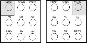
5 Pin Configuration and Functions
YFQ Package
9-Pin DSBGA
Top View (left); Bottom View (right)

Pin Functions
| PIN | TYPE | DESCRIPTION | |
|---|---|---|---|
| NUMBER | NAME | ||
| A1 | VCON | A/I | Voltage control analog input. VCON controls VOUT in PWM and ECO modes. VCON may also be used to force bypass condition by setting VCON > VIN/2.5. |
| A2 | SGND | G | Signal ground for analog and control circuitry. |
| A3 | PGND | G | Power ground for the power MOSFETs and gate drive circuitry |
| B1 | EN | D/I | Enable Input. Set this digital input high for normal operation. For shutdown, set low. Do not leave EN pin floating. |
| B2 | NC | — | Do not connect to PGND directly — Internally connected to SGND. |
| B3 | SW | P/O | Switching node connection to the internal PFET switch and NFET synchronous rectifier. Connect to an inductor with a saturation current rating that exceeds the maximum Switch Peak Current Limit specification of the LM3242. |
| C1 | BPEN | D/I | Bypass Enable input. Set this digital input high to force bypass operation. For normal operation with automatic bypass, set low or connect to ground. Do not leave this pin floating. |
| C2 | FB | A | Feedback analog input and bypass FET output. Connect to the output at the output filter capacitor. |
| C3 | VIN | P/I | Voltage supply input for SMPS converter. |