SNVS875O August 2012 – December 2015 LM3262
PRODUCTION DATA.
- 1 Features
- 2 Applications
- 3 Description
- 4 Revision History
- 5 Pin Configuration and Functions
- 6 Specifications
- 7 Detailed Description
- 8 Application and Implementation
- 9 Power Supply Recommendations
- 10Layout
- 11Device and Documentation Support
- 12Mechanical, Packaging, and Orderable Information
5 Pin Configuration and Functions
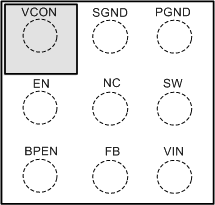
YFQ Package
9-Pin DSBGA
Top View

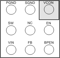
YFQ Package
9-Pin DSBGA
Bottom View

Pin Functions
| PIN | TYPE | DESCRIPTION | |
|---|---|---|---|
| NO. | NAME | ||
| A1 | VCON | Analog | Voltage control analog input. VCON controls VOUT in PWM and ECO modes. VCON may also be used to force the device into sleep mode by setting VCON < 80 mV or into bypass condition by setting VCON > 1.5 V. |
| A2 | SGND | Ground | Signal ground for analog and control circuitry. |
| A3 | PGND | Ground | Power ground for the Power MOSFETs and gate drive circuitry |
| B1 | EN | Digital/Input | Enable Input. Set this digital input high for normal operation. For shutdown, set low. Do not leave EN pin floating. |
| B2 | NC | — | Do not connect to PGND directly — Internally connected to SGND. |
| B3 | SW | Analog | Switching node connection to the internal PFET switch and NFET synchronous rectifier. Connect to an inductor with a saturation current rating that exceeds the maximum switch peak current limit specification of the LM3262. |
| C1 | BPEN | Input | Bypass enable input. Set this digital input high to force bypass operation. For normal operation with automatic bypass, set low or connect to ground. Do not leave this pin floating. |
| C2 | FB | Analog | Feedback analog input and bypass FET output. Connect to the output at the output filter capacitor. |
| C3 | VIN | Input | Voltage supply input for SMPS converter. |