JAJSFC4
April 2018
LM3478Q-Q1
PRODUCTION DATA.
1
特長
2
アプリケーション
3
概要
Device Images
一般的な高効率昇圧(ブースト)コンバータ
4
改訂履歴
5
Pin Configuration and Functions
Pin Functions
6
Specifications
6.1
Absolute Maximum Ratings
6.2
ESD Ratings - LM3478Q-Q1
6.3
Recommended Operating Conditions
6.4
Thermal Information
6.5
Electrical Characteristics
6.6
Typical Characteristics
7
Detailed Description
7.1
Overview
7.2
Functional Block Diagram
7.3
Feature Description
7.3.1
Overvoltage Protection
7.3.2
Slope Compensation Ramp
7.3.3
Frequency Adjust/Shutdown
7.3.4
Short-Circuit Protection
7.4
Device Functional Modes
8
Application and Implementation
8.1
Application Information
8.2
Typical Applications
8.2.1
Typical High Efficiency Step-Up (Boost) Converter
8.2.1.1
Design Requirements
8.2.1.2
Detailed Design Procedure
8.2.1.2.1
Custom Design with WEBENCH Tools
8.2.1.2.2
Power Inductor Selection
8.2.1.2.3
Programming the Output Voltage
8.2.1.2.4
Setting the Current Limit
8.2.1.2.5
Current Limit with External Slope Compensation
8.2.1.2.6
Power Diode Selection
8.2.1.2.7
Power MOSFET Selection
8.2.1.2.8
Input Capacitor Selection
8.2.1.2.9
Output Capacitor Selection
8.2.1.2.10
Compensation
8.2.1.3
Application Curves
8.2.2
Typical SEPIC Converter
8.2.2.1
Design Requirements
8.2.2.2
Detailed Design Procedure
8.2.2.2.1
Power MOSFET Selection
8.2.2.2.2
Power Diode Selection
8.2.2.2.3
Selection of Inductors L1 and L2
8.2.2.2.4
Sense Resistor Selection
8.2.2.2.5
Sepic Capacitor Selection
8.2.2.2.6
Input Capacitor Selection
8.2.2.2.7
Output Capacitor Selection
8.2.2.3
Application Curves
9
Power Supply Recommendations
10
Layout
10.1
Layout Guidelines
10.2
Layout Example
11
デバイスおよびドキュメントのサポート
11.1
WEBENCHツールによるカスタム設計
11.2
ドキュメントの更新通知を受け取る方法
11.3
ドキュメントのサポート
11.3.1
関連資料
11.4
商標
11.5
静電気放電に関する注意事項
11.6
Glossary
12
メカニカル、パッケージ、および注文情報
パッケージ・オプション
メカニカル・データ(パッケージ|ピン)
DGK|8
MPDS028E
サーマルパッド・メカニカル・データ
発注情報
jajsfc4_oa
jajsfc4_pm
6.6
Typical Characteristics
Unless otherwise specified, V
IN
= 12V, T
J
= 25°C.
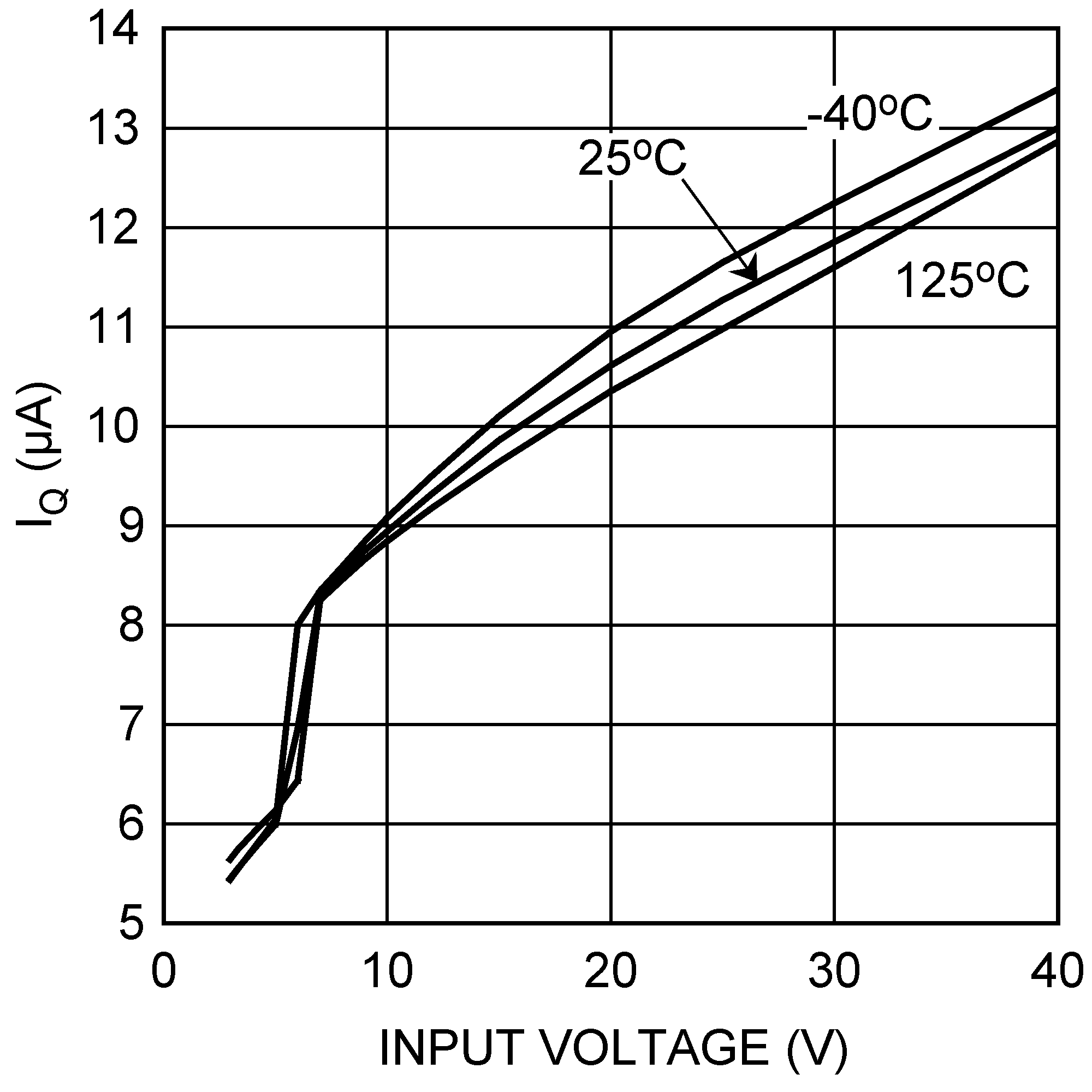
Figure 1.
I
Q
vs Input Voltage (Shutdown)
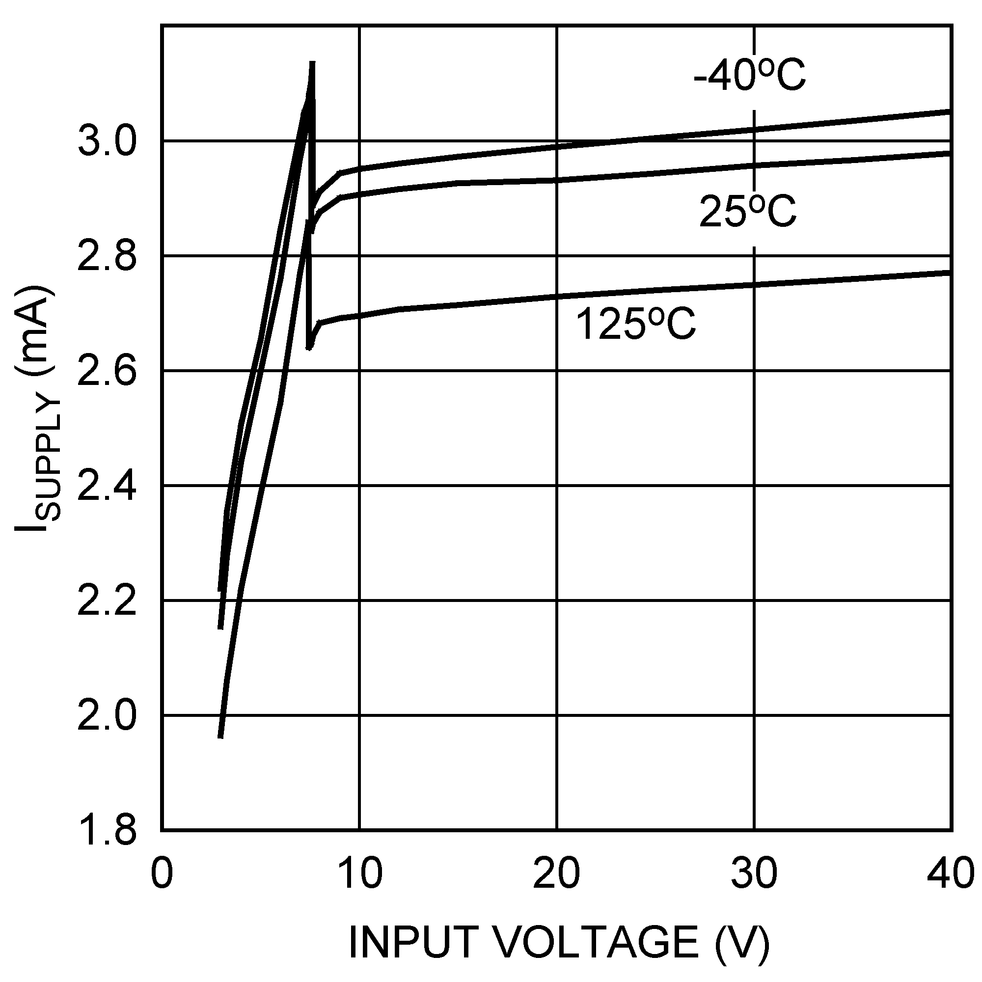
Figure 3.
I
Supply
vs V
IN
(Switching)
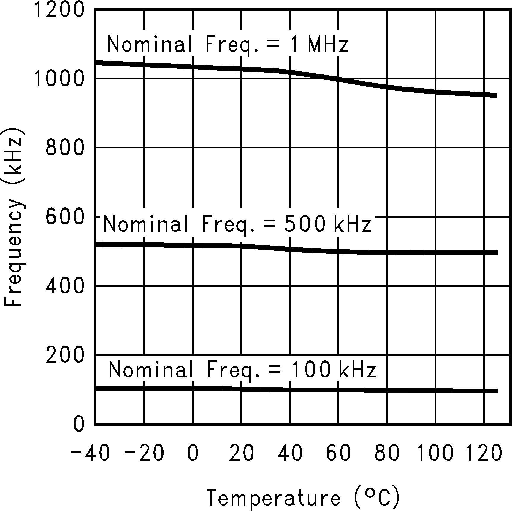
Figure 5.
Frequency vs Temperature
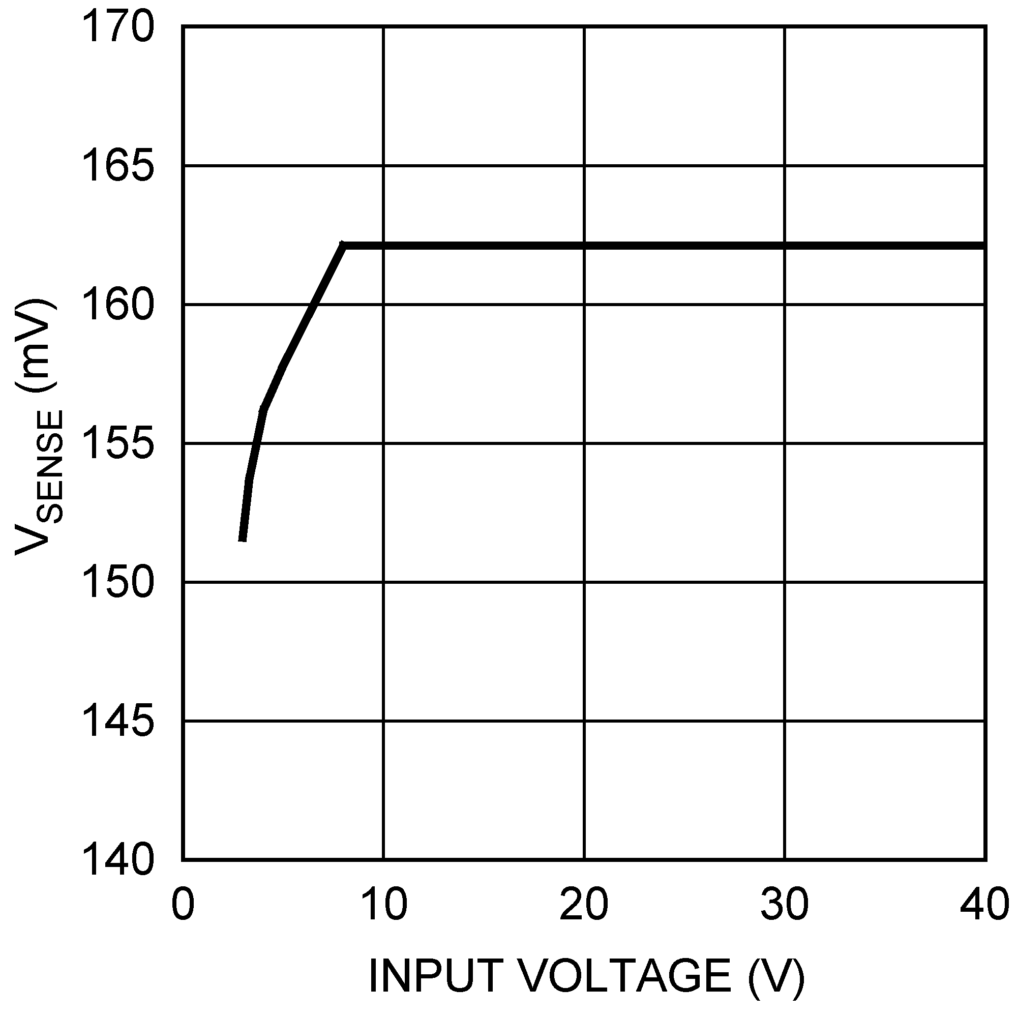
Figure 7.
Current Sense Threshold vs Input Voltage
Figure 9.
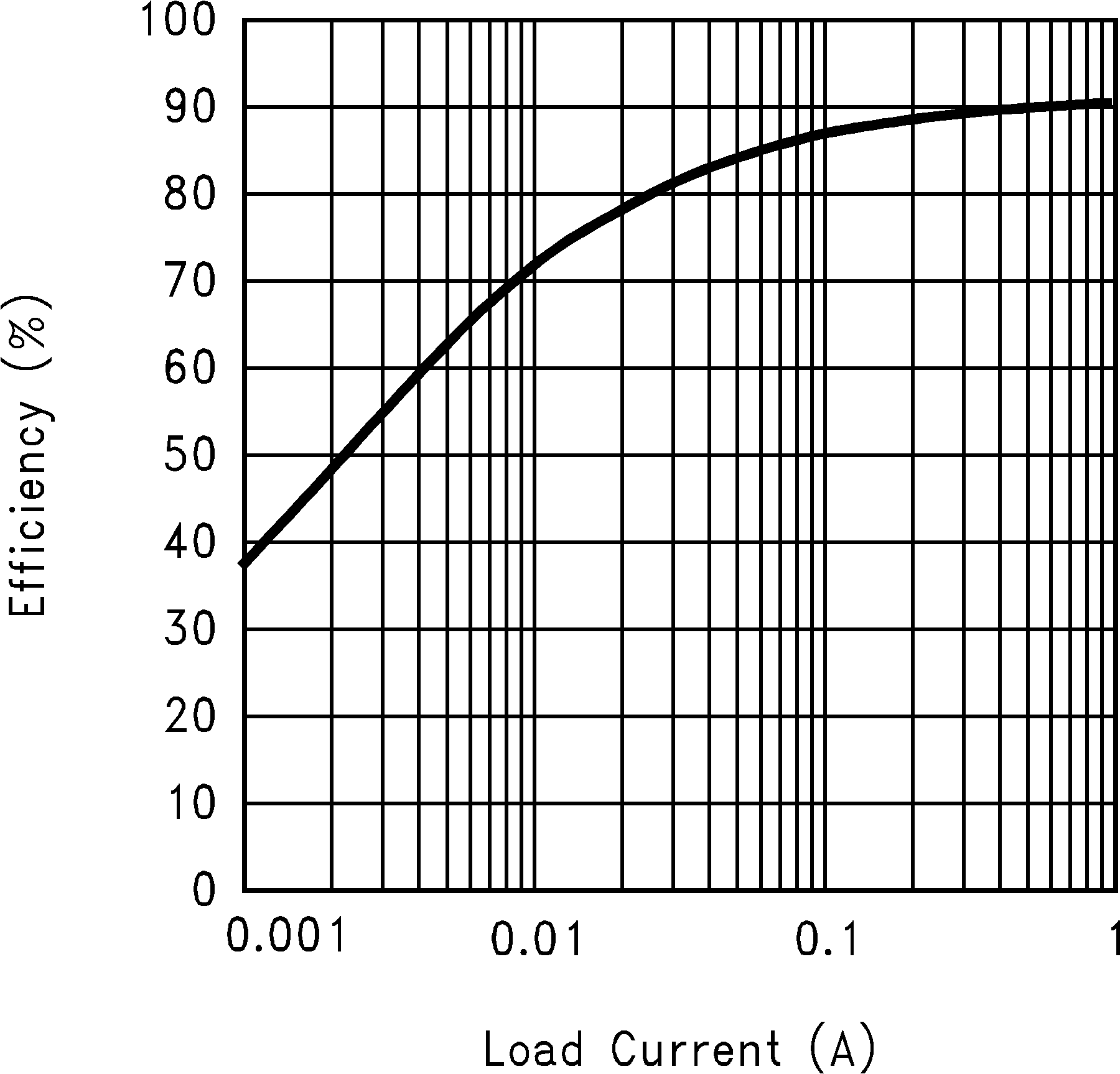
Efficiency vs Load Current (3.3-V Input and 12-V Output)
Figure 11.
Efficiency vs Load Current (9-V Input and 12-V Output)
Figure 13.
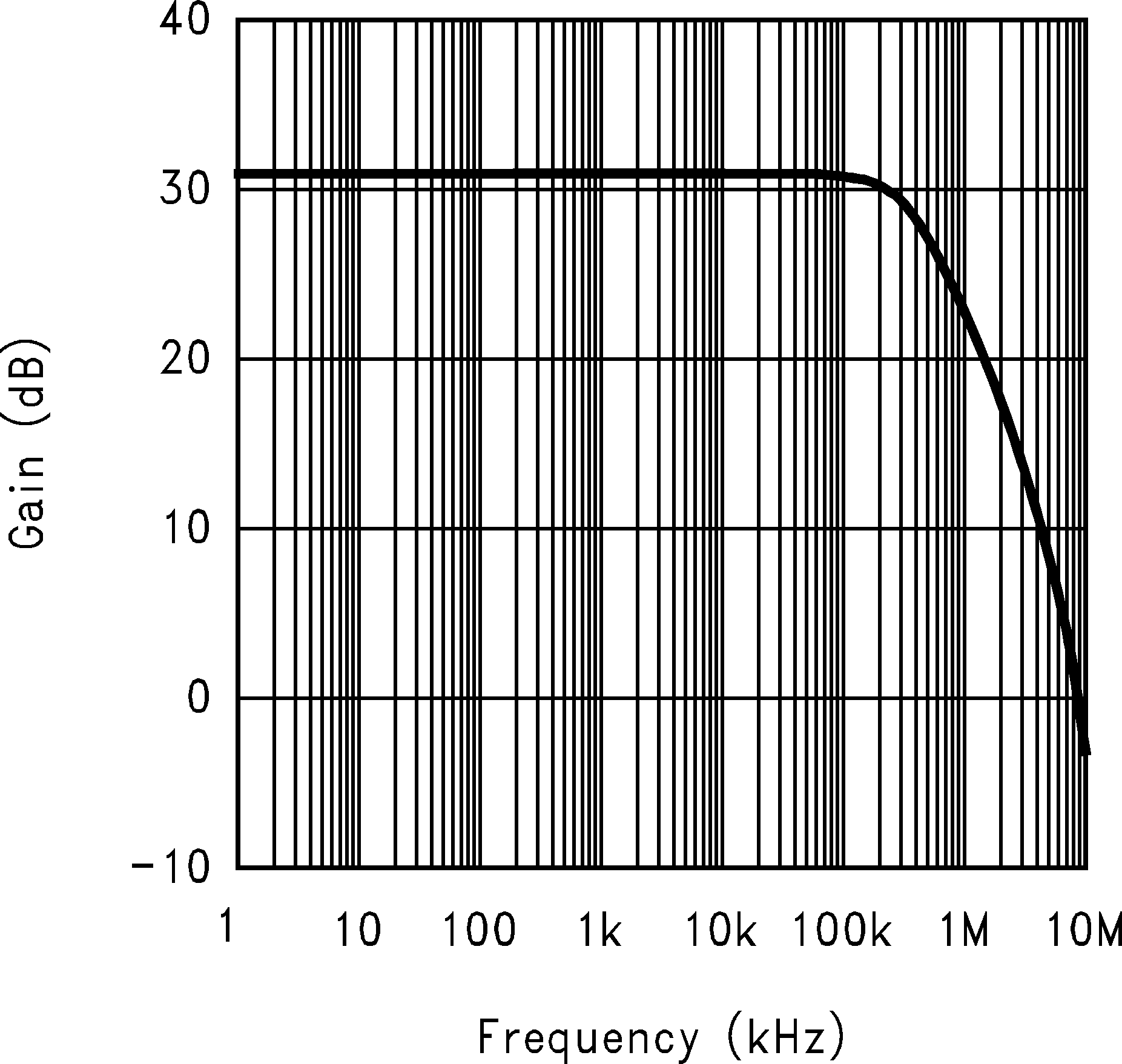
Error Amplifier Gain
Figure 15.
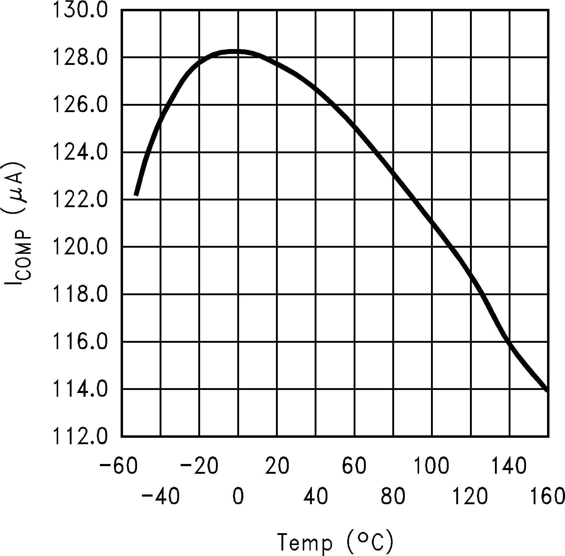
COMP Pin Source Current vs Temperature
Figure 17.
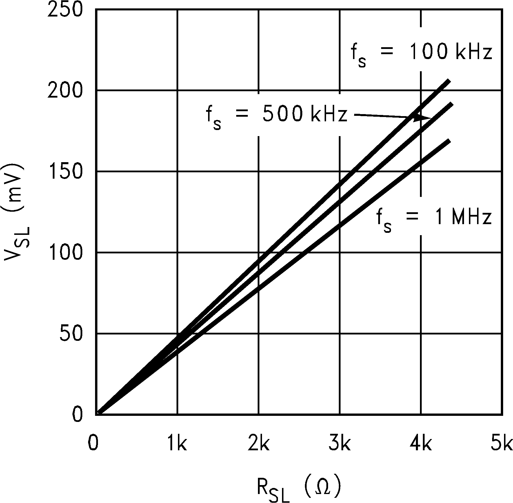
Compensation Ramp vs Compensation Resistor
Figure 19.
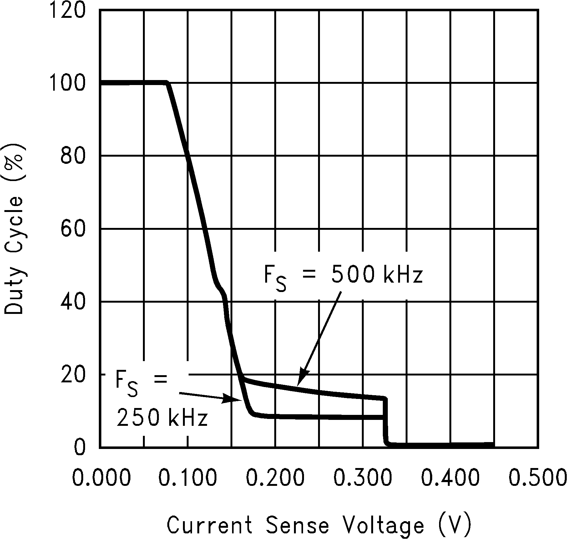
Duty Cycle vs Current Sense Voltage
Figure 2.
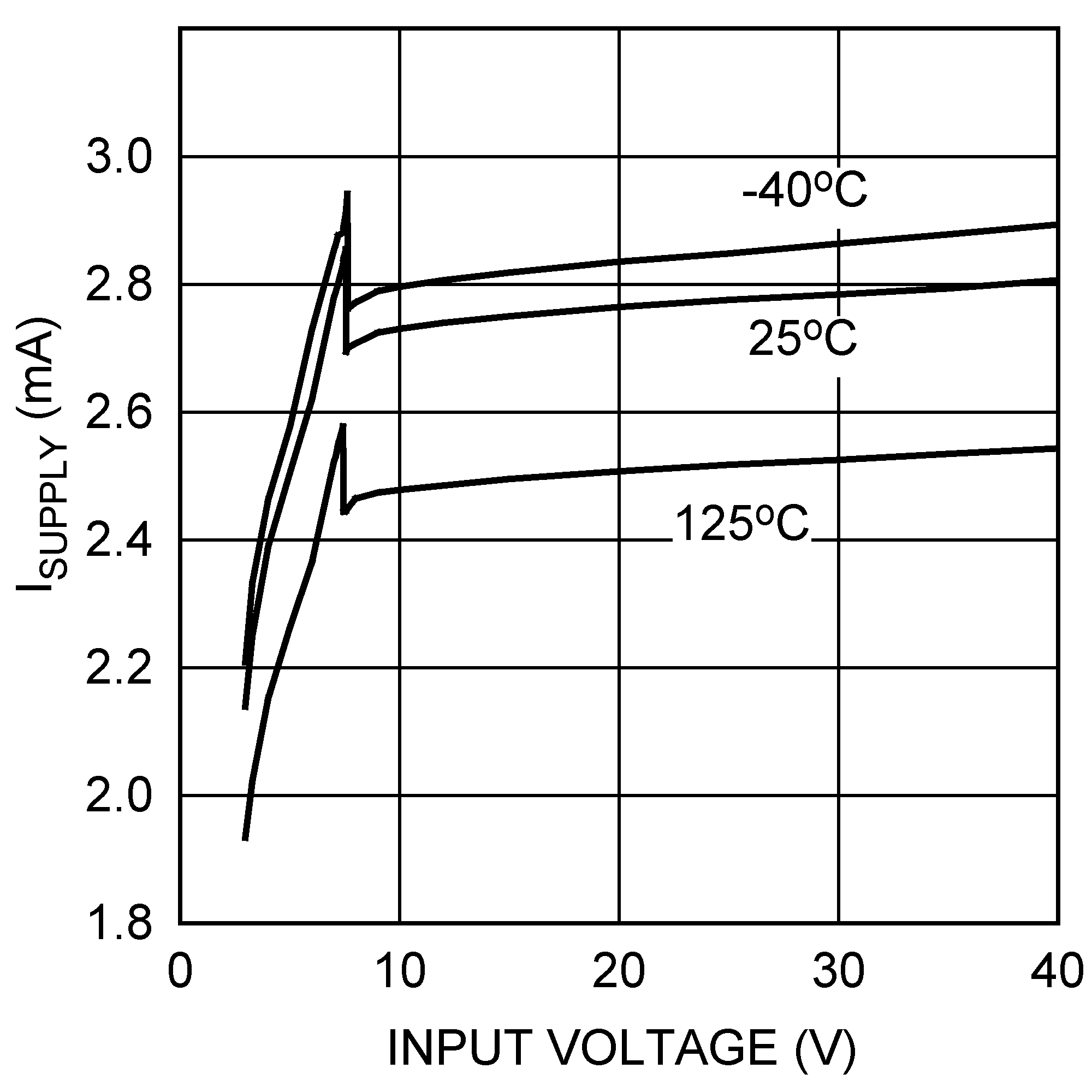
I
Supply
vs Input Voltage (Non-Switching)
Figure 4.
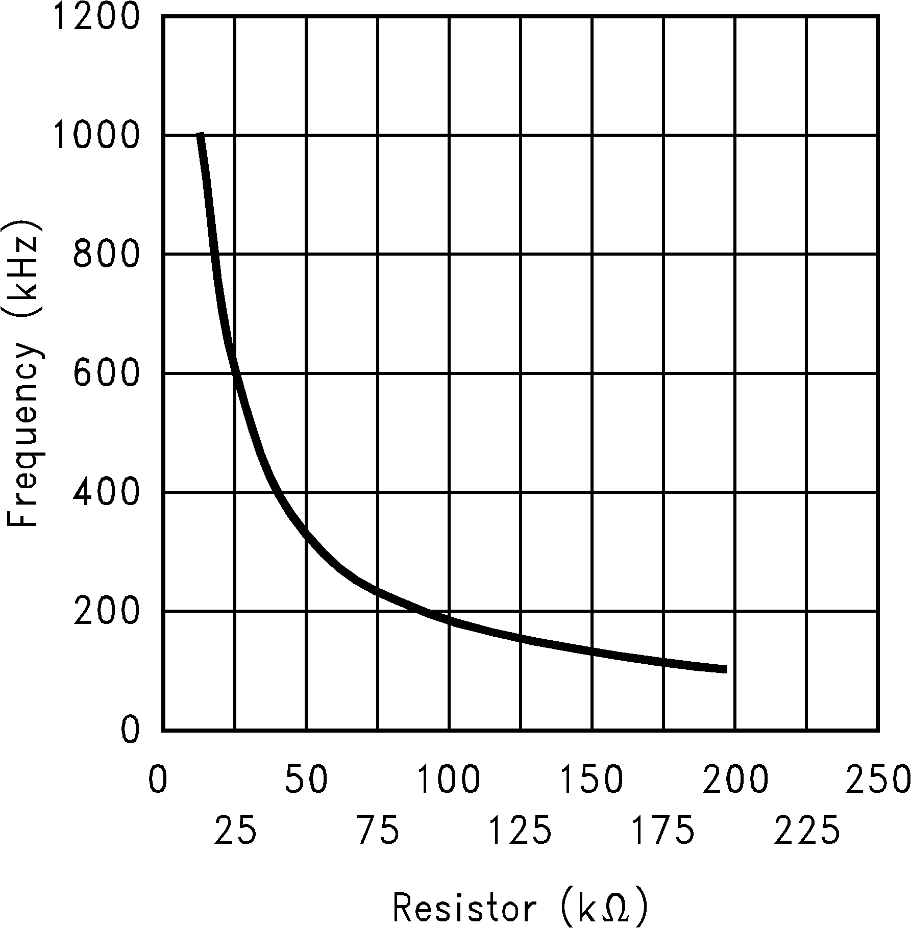
Switching Frequency vs R
FA
Figure 6.
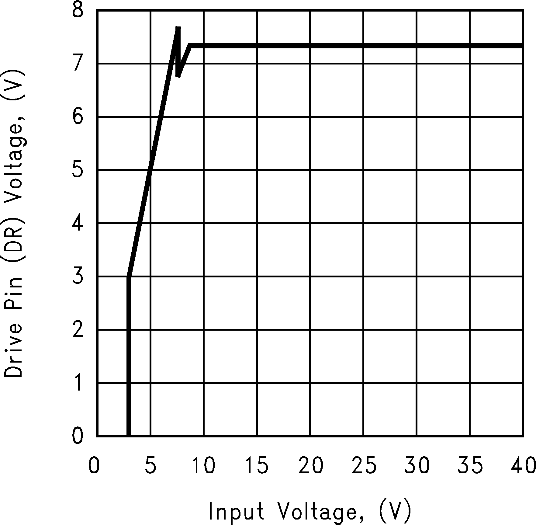
Drive Voltage vs Input Voltage
Figure 8.
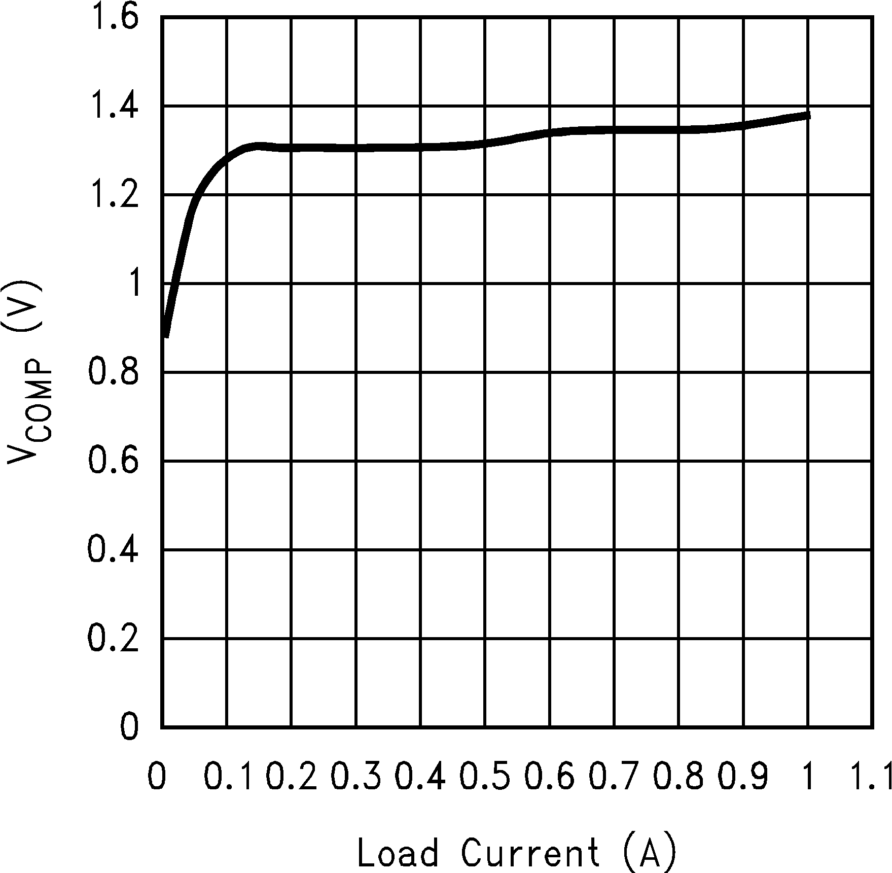
COMP Pin Voltage vs Load Current
Figure 10.
Efficiency vs Load Current (5-V Input and 12-V Output)
Figure 12.
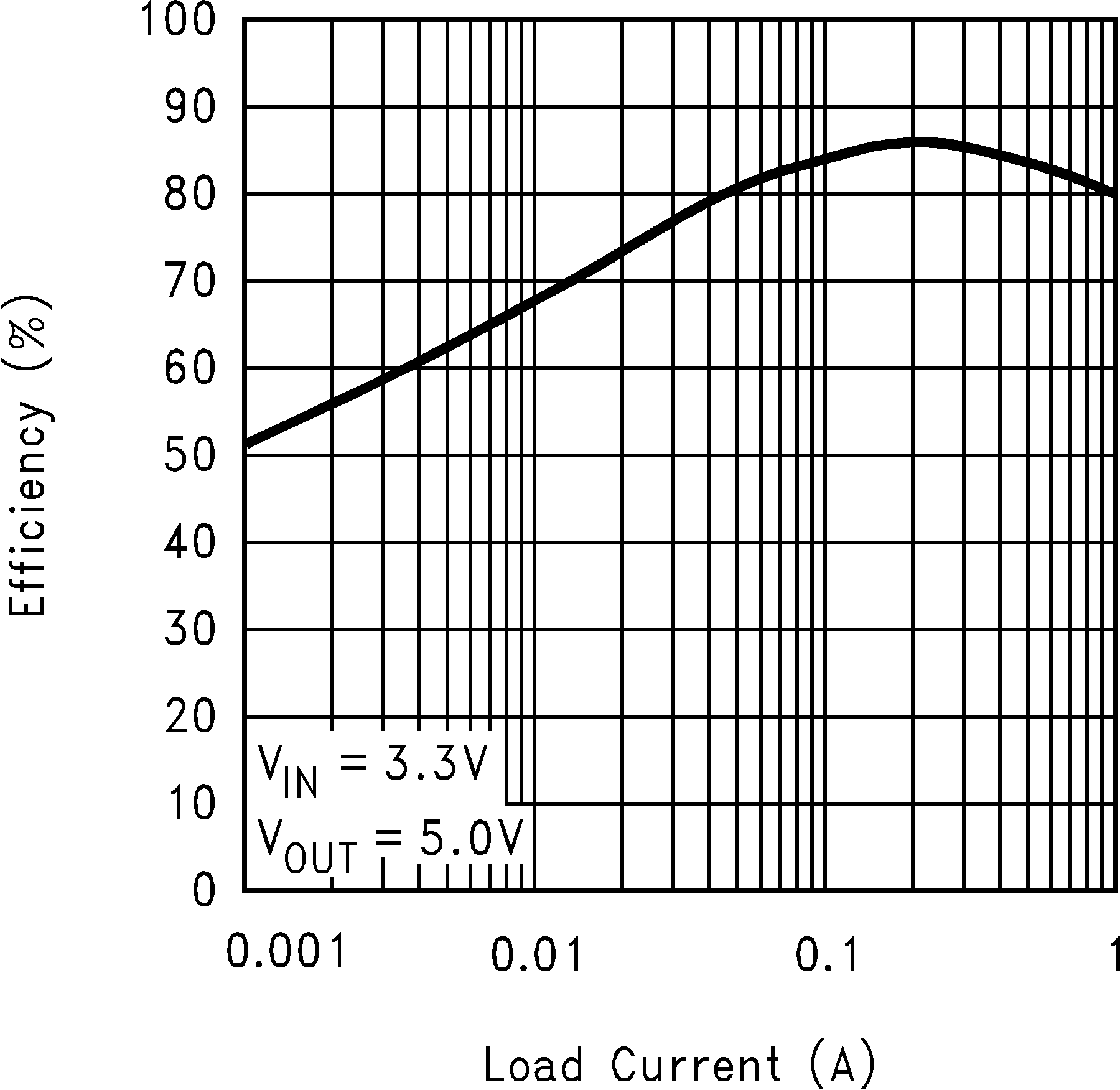
Efficiency vs Load Current (3.3-V Input and 5-V Output)
Figure 14.
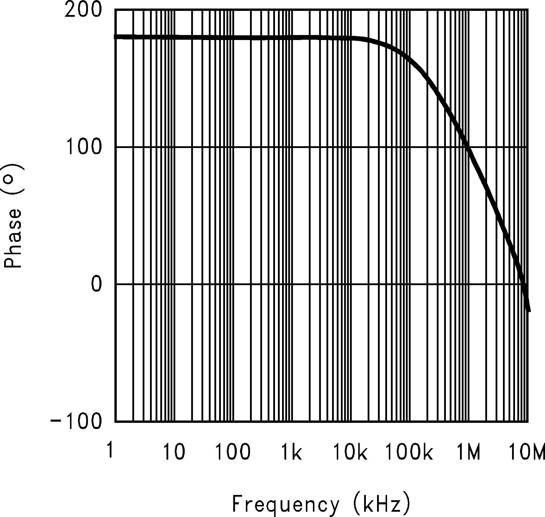
Error Amplifier Phase
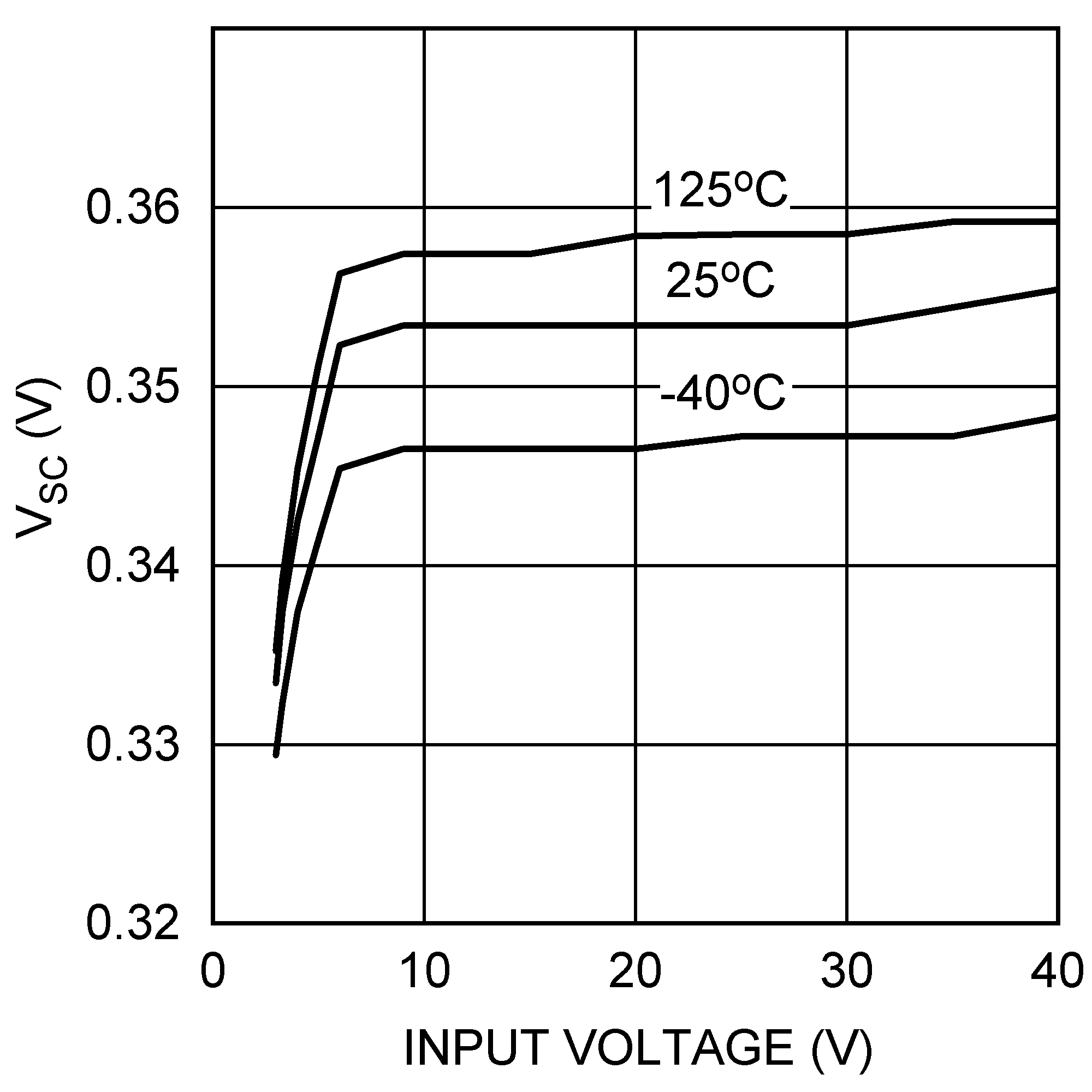
Figure 16.
Short Circuit Sense Voltage vs Input Voltage
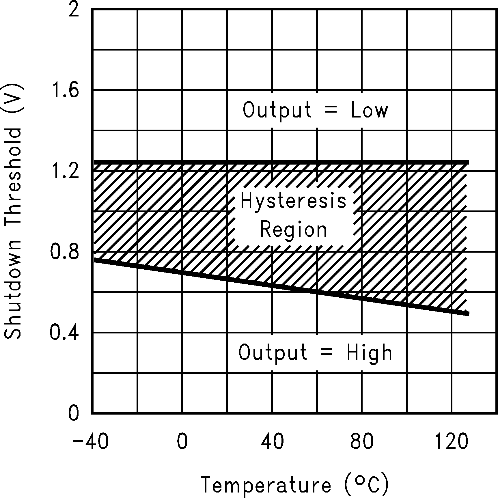
Figure 18.
Shutdown Threshold Hysteresis vs Temperature