JAJSIL9A February 2020 – July 2020 LM76005-Q1
PRODUCTION DATA
- 1 特長
- 2 アプリケーション
- 3 概要
- 4 Revision History
- 5 Pin Configuration and Functions
- 6 Specifications
-
7 Detailed Description
- 7.1 Overview
- 7.2 Functional Block Diagram
- 7.3
Feature Description
- 7.3.1 Fixed-Frequency, Peak-Current-Mode Control
- 7.3.2 Light Load Operation Modes — PFM and FPWM
- 7.3.3 Adjustable Output Voltage
- 7.3.4 Enable (EN Pin) and UVLO
- 7.3.5 Internal LDO, VCC UVLO, and Bias Input
- 7.3.6 Soft Start and Voltage Tracking (SS/TRK)
- 7.3.7 Adjustable Switching Frequency (RT) and Frequency Synchronization
- 7.3.8 Minimum On-Time, Minimum Off-Time, and Frequency Foldback at Dropout Conditions
- 7.3.9 Bootstrap Voltage and VBOOT UVLO (BOOT Pin)
- 7.3.10 Power Good and Overvoltage Protection (PGOOD)
- 7.3.11 Overcurrent and Short-Circuit Protection
- 7.3.12 Thermal Shutdown
- 7.4 Device Functional Modes
-
8 Application and Implementation
- 8.1 Application Information
- 8.2
Typical Applications
- 8.2.1 Design Requirements
- 8.2.2
Detailed Design Procedure
- 8.2.2.1 Custom Design With WEBENCH® Tools
- 8.2.2.2 Output Voltage Setpoint
- 8.2.2.3 Switching Frequency
- 8.2.2.4 Input Capacitors
- 8.2.2.5 Inductor Selection
- 8.2.2.6 Output Capacitor Selection
- 8.2.2.7 Feedforward Capacitor
- 8.2.2.8 Bootstrap Capacitors
- 8.2.2.9 VCC Capacitors
- 8.2.2.10 BIAS Capacitors
- 8.2.2.11 Soft-Start Capacitors
- 8.2.2.12 Undervoltage Lockout Setpoint
- 8.2.2.13 PGOOD
- 8.2.2.14 Synchronization
- 8.2.3 Application Curves
- 9 Power Supply Recommendations
- 10Layout
- 11Device and Documentation Support
- 12Mechanical, Packaging, and Orderable Information
パッケージ・オプション
メカニカル・データ(パッケージ|ピン)
- RNP|30
サーマルパッド・メカニカル・データ
- RNP|30
発注情報
3 概要
LM76005-Q1 レギュレータは、最高 60V の入力から最大 5A (LM76005-Q1) の負荷電流を駆動できる、使いやすい同期整流降圧型 DC-DC コンバータです。65V 許容であるため、入力サージ保護が簡単です。
LM76005-Q1 は、ピーク電流モード制御を使用して、小さいソリューション・サイズで非常に高い効率と出力精度を実現します。PWM モードと PFM モードの間のシームレスな移行、非常に小さな MOSFET ON 抵抗、外部バイアス入力により、負荷範囲全体にわたって非常に優れた効率が得られます。
このデバイスは、必要な外付けコンポーネントが少なく、PCB レイアウトが単純になるようにピン配置が設計されており、クラス最高の EMI (CISPR25) および熱性能を実現しています。LM76005-Q1 の小さなソリューション・サイズと機能セットは、広範な最終機器を簡単に実装できるように設計されています。
LM76005-Q1 デバイスは、ウェッタブル・フランク付きの WQFN 30 ピン・リードレス・パッケージで供給されます。
製品情報
| 部品番号(1) | パッケージ | 本体サイズ (公称) |
|---|---|---|
| LM76005-Q1 | WQFN (30) | 6.00mm × 4.00mm |
(1) 利用可能なすべてのパッケージについては、このデータシートの末尾にある注文情報を参照してください。
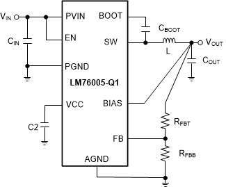
 概略回路図
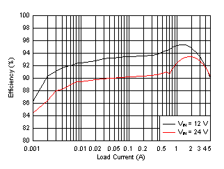
概略回路図 効率:VOUT = 5V、fSW = 400kHz、自動モード