JAJSK05D September   2020  – March 2022 LMG3422R030 , LMG3425R030

PRODUCTION DATA  

  1. 特長
  2. アプリケーション
  3. 概要
  4. Revision History
  5. Device Comparison
  6. Pin Configuration and Functions
  7. Specifications
    1. 7.1 Absolute Maximum Ratings
    2. 7.2 ESD Ratings
    3. 7.3 Recommended Operating Conditions
    4. 7.4 Thermal Information
    5. 7.5 Electrical Characteristics
    6. 7.6 Switching Characteristics
    7. 7.7 Typical Characteristics
  8. Parameter Measurement Information
    1. 8.1 Switching Parameters
      1. 8.1.1 Turn-On Times
      2. 8.1.2 Turn-Off Times
      3. 8.1.3 Drain-Source Turn-On Slew Rate
      4. 8.1.4 Turn-On and Turn-Off Switching Energy
  9. Detailed Description
    1. 9.1 Overview
    2. 9.2 Functional Block Diagram
    3. 9.3 Feature Description
      1. 9.3.1  GaN FET Operation Definitions
      2. 9.3.2  Direct-Drive GaN Architecture
      3. 9.3.3  Drain-Source Voltage Capability
      4. 9.3.4  Internal Buck-Boost DC-DC Converter
      5. 9.3.5  VDD Bias Supply
      6. 9.3.6  Auxiliary LDO
      7. 9.3.7  Fault Detection
        1. 9.3.7.1 Overcurrent Protection and Short-Circuit Protection
        2. 9.3.7.2 Overtemperature Shutdown
        3. 9.3.7.3 UVLO Protection
        4. 9.3.7.4 Fault Reporting
      8. 9.3.8  Drive Strength Adjustment
      9. 9.3.9  Temperature-Sensing Output
      10. 9.3.10 Ideal-Diode Mode Operation
    4. 9.4 Device Functional Modes
  10. 10Application and Implementation
    1. 10.1 Application Information
    2. 10.2 Typical Application
      1. 10.2.1 Design Requirements
      2. 10.2.2 Detailed Design Procedure
        1. 10.2.2.1 Slew Rate Selection
          1. 10.2.2.1.1 Start-Up and Slew Rate With Bootstrap High-Side Supply
        2. 10.2.2.2 Signal Level-Shifting
        3. 10.2.2.3 Buck-Boost Converter Design
      3. 10.2.3 Application Curves
    3. 10.3 Do's and Don'ts
  11. 11Power Supply Recommendations
    1. 11.1 Using an Isolated Power Supply
    2. 11.2 Using a Bootstrap Diode
      1. 11.2.1 Diode Selection
      2. 11.2.2 Managing the Bootstrap Voltage
  12. 12Layout
    1. 12.1 Layout Guidelines
      1. 12.1.1 Solder-Joint Reliability
      2. 12.1.2 Power-Loop Inductance
      3. 12.1.3 Signal-Ground Connection
      4. 12.1.4 Bypass Capacitors
      5. 12.1.5 Switch-Node Capacitance
      6. 12.1.6 Signal Integrity
      7. 12.1.7 High-Voltage Spacing
      8. 12.1.8 Thermal Recommendations
    2. 12.2 Layout Examples
  13. 13Device and Documentation Support
    1. 13.1 Documentation Support
      1. 13.1.1 Related Documentation
    2. 13.2 Receiving Notification of Documentation Updates
    3. 13.3 サポート・リソース
    4. 13.4 Trademarks
    5. 13.5 Electrostatic Discharge Caution
    6. 13.6 Export Control Notice
    7. 13.7 Glossary
  14. 14Mechanical, Packaging, and Orderable Information

パッケージ・オプション

デバイスごとのパッケージ図は、PDF版データシートをご参照ください。

メカニカル・データ(パッケージ|ピン)
  • RQZ|54
サーマルパッド・メカニカル・データ
発注情報

概要

ドライバおよび保護機能を内蔵した LMG342xR030 GaN FET を使うと、設計者はパワー・エレクトロニクス・システムにおいて、比類ない電力密度と効率を実現できます。

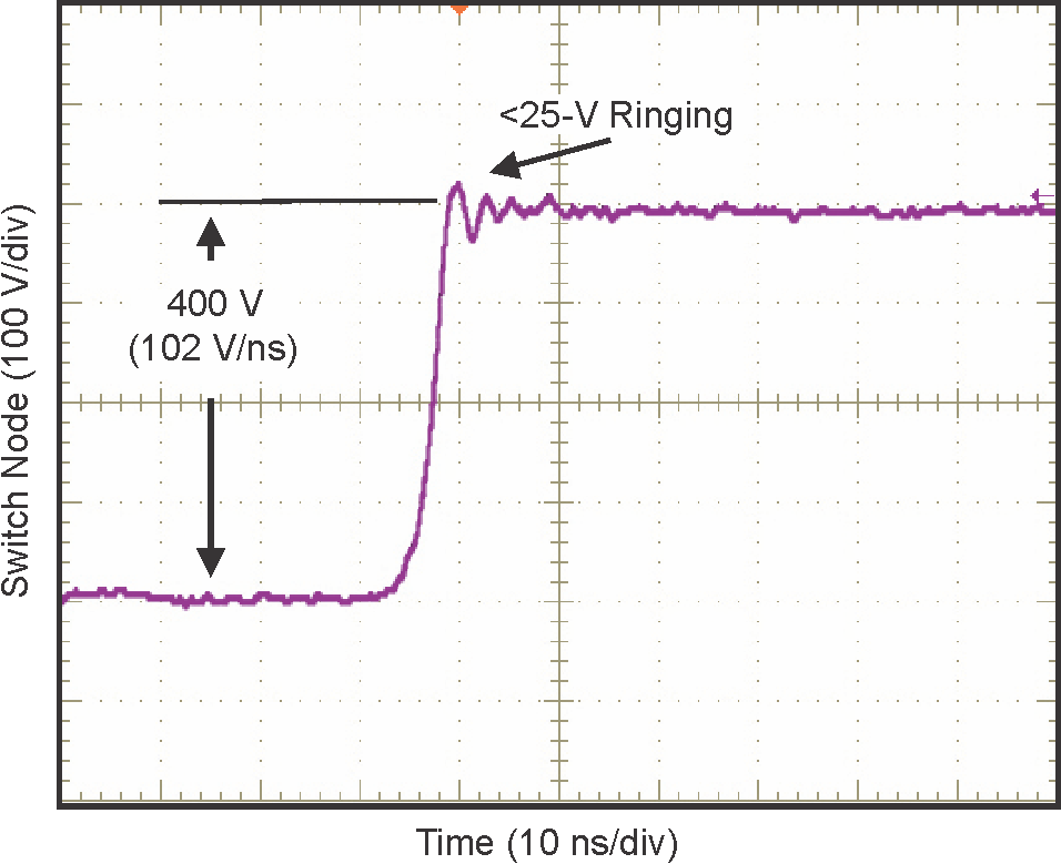
LMG342xR030 は、最大 150V/ns のスイッチング速度を実現できるシリコン・ドライバを内蔵しています。TI の統合型高精度ゲート・バイアスは、ディスクリート・シリコン・ゲート・ドライバと比較して、より広いスイッチング SOA をもたらします。この統合と TI の低インダクタンス・パッケージの組み合わせにより、ハード・スイッチング電源トポロジでもノイズの少ないスイッチングとリンギングの最小化を実現できます。調整可能なゲート・ドライブ強度により、20V/ns~150V/ns までのスルーレートの制御が可能で、EMI のアクティブ制御とスイッチング性能の最適化に使用できます。LMG3425R030 は理想ダイオード・モードを備えているため、アダプティブ・デッドタイム制御が可能で、第 3 象限の損失を低減します。

高度な電源管理機能として、デジタル温度通知とフォルト検出を備えています。GaN FET の温度は可変デューティ・サイクル PWM 出力により通知されるため、デバイスの負荷の管理が簡単になります。報告されるフォルトには、過熱、過電流、UVLO の監視があります。

デバイス情報
部品番号 パッケージ (1) 本体サイズ (公称)
LMG3422R030 VQFN (54) 12.00mm × 12.00mm
LMG3425R030
利用可能なすべてのパッケージについては、このデータシートの末尾にある注文情報を参照してください。
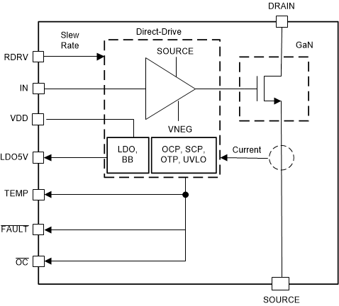
GUID-56727E62-3C5A-489B-87F9-87E74F3E3739-low.gif概略ブロック図
GUID-3620467C-741C-47F7-9267-9B23B885C3BE-low.png100V/ns を超えるスイッチング性能