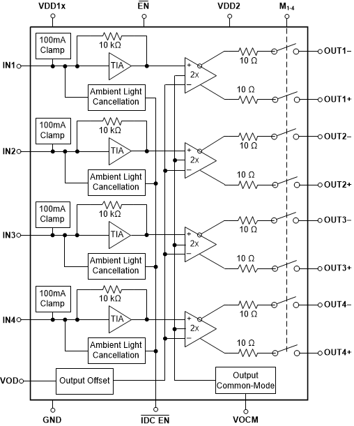
LMH32404-Q1 は、LIDAR (光検出と測距) アプリケーションとレーザー距離測定システムのための、クワッド・チャネル、シングルエンド入力、差動出力のトランスインピーダンス・アンプ (TIA) です。
LMH32404-Q1 は、過負荷入力状態において、アンプを保護し、迅速にデバイスを回復させることができる 100mA のクランプを各チャネルに内蔵しています。LMH32404-Q1 は、フォトダイオードとアンプの間の AC 結合の代わりに使用できる環境光キャンセル (ALC) 回路も各チャネルに内蔵しているため、基板面積とシステム・コストを削減できます。DC および低周波数成分を測定するときは、 ALC ループを無効にしてください。
各 LMH32404-Q1 チャネルの出力にはスイッチが内蔵されており、このスイッチにより、差動出力アンプは出力ピンから切断され、チャネルはスタンバイ・モードに移行します。異なるチャネル間で切り替える場合の遷移時間はわずか 10ns です。LMH32404-Q1 は EN ピンを使って低消費電力モードに移行させることができ、アンプを使用していないときに電力を節約できます。
部品番号 | パッケージ | 本体サイズ (公称) |
---|---|---|
LMH32404-Q1 | VQFN (28) | 5.00mm × 4.00mm |
Changes from Revision * (December 2020) to Revision A (November 2021)
PIN | I/O | DESCRIPTION | |
---|---|---|---|
NAME | NO. | ||
EN | 9 | I | Device enable pin. EN = logic low = normal operation (default); EN = logic high = low power mode.(1) |
GND | 11,26 | I | Amplifier ground. |
IDC_EN | 28 | I | Ambient light cancellation loop enable. IDC_EN = logic low = enable DC cancellation (default); IDC_EN = logic high = disable DC cancellation.(1) |
IN1 | 1 | I | Transimpedance amplifier input - Channel 1. |
IN2 | 3 | I | Transimpedance amplifier input - Channel 2. |
IN3 | 6 | I | Transimpedance amplifier input - Channel 3. |
IN4 | 8 | I | Transimpedance amplifier input - Channel 4. |
M1 | 25 | I | Select Channel 1. M1 = logic high = Channel 1 operational and output switches closed. M1 = logic low (default) = Channel 1 in standby power mode and output switches open. (1) |
M2 | 24 | I | Select Channel 2. M2 = logic high = Channel 2 operational and output switches closed. M2 = logic low (default) = Channel 2 in standby power mode and output switches open. (1) |
M3 | 13 | I | Select Channel 3. M3 = logic high = Channel 3 operational and output switches closed. M3 = logic low (default) = Channel 3 in standby power mode and output switches open. (1) |
M4 | 12 | I | Select Channel 4. M4 = logic high = Channel 4 operational and output switches closed. M4 = logic low (default) = Channel 4 in standby power mode and output switches open. (1) |
OUT1– | 22 | O | Channel 1 inverting amplifier output. When light is incident on the photodiode the output pin transitions in a negative direction from the no light condition. |
OUT1+ | 21 | O | Channel 1 noninverting amplifier output. When light is incident on the photodiode the output pin transitions in a positive direction from the no light condition. |
OUT2– | 20 | O | Channel 2 inverting amplifier output. When light is incident on the photodiode the output pin transitions in a negative direction from the no light condition. |
OUT2+ | 19 | O | Channel 2 noninverting amplifier output. When light is incident on the photodiode the output pin transitions in a positive direction from the no light condition. |
OUT3– | 18 | O | Channel 3 inverting amplifier output. When light is incident on the photodiode the output pin transitions in a negative direction from the no light condition. |
OUT3+ | 17 | O | Channel 3 noninverting amplifier output. When light is incident on the photodiode the output pin transitions in a positive direction from the no light condition. |
OUT4– | 16 | O | Channel 4 inverting amplifier output. When light is incident on the photodiode the output pin transitions in a negative direction from the no light condition. |
OUT4+ | 15 | O | Channel 4 noninverting amplifier output. When light is incident on the photodiode the output pin transitions in a positive direction from the no light condition. |
VDD1 | 2, 4, 5, 7 | I | Positive power supply for the transimpedance amplifier stage. Each pin should be tied to the same power supply with independent power-supply bypassing. |
VDD2 | 14,23 | I | Positive power supply for the differential amplifier stage. Tie VDD1 and VDD2 to the same power supply with independent power-supply bypassing. |
VOCM | 27 | I | Differential amplifier common-mode output control. |
VOD | 10 | I | Differential amplifier differential output offset control. |
Thermal pad | — | Connect the thermal pad to the same potential as pin 11 and 26 (GND). |