JAJSQ22J september 2011 – may 2023 LMK00301
PRODUCTION DATA
- 1
- 1 特長
- 2 アプリケーション
- 3 概要
- 4 Revision History
- 5 Device Comparison
- 6 Pin Configuration and Functions
- 7 Specifications
- 8 Parameter Measurement Information
- 9 Detailed Description
- 10Application and Implementation
- 11Power Supply Recommendations
- 12Layout
- 13Device and Documentation Support
- 14Mechanical, Packaging, and Orderable Information
パッケージ・オプション
メカニカル・データ(パッケージ|ピン)
- RHS|48
サーマルパッド・メカニカル・データ
- RHS|48
発注情報
7.6 Typical Characteristics
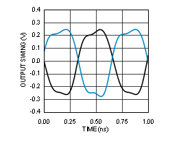
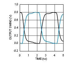
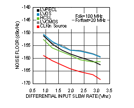
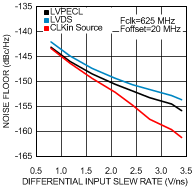
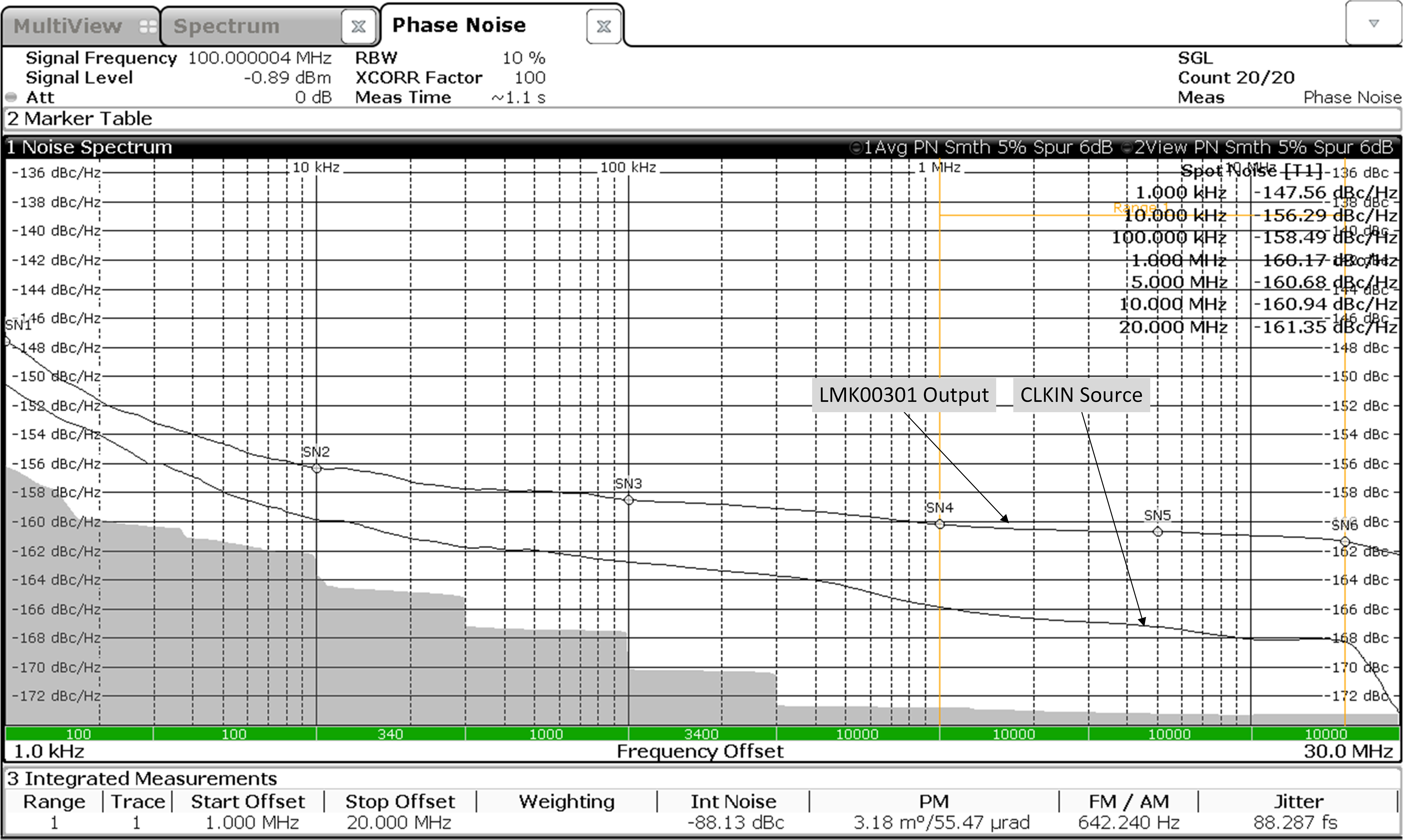
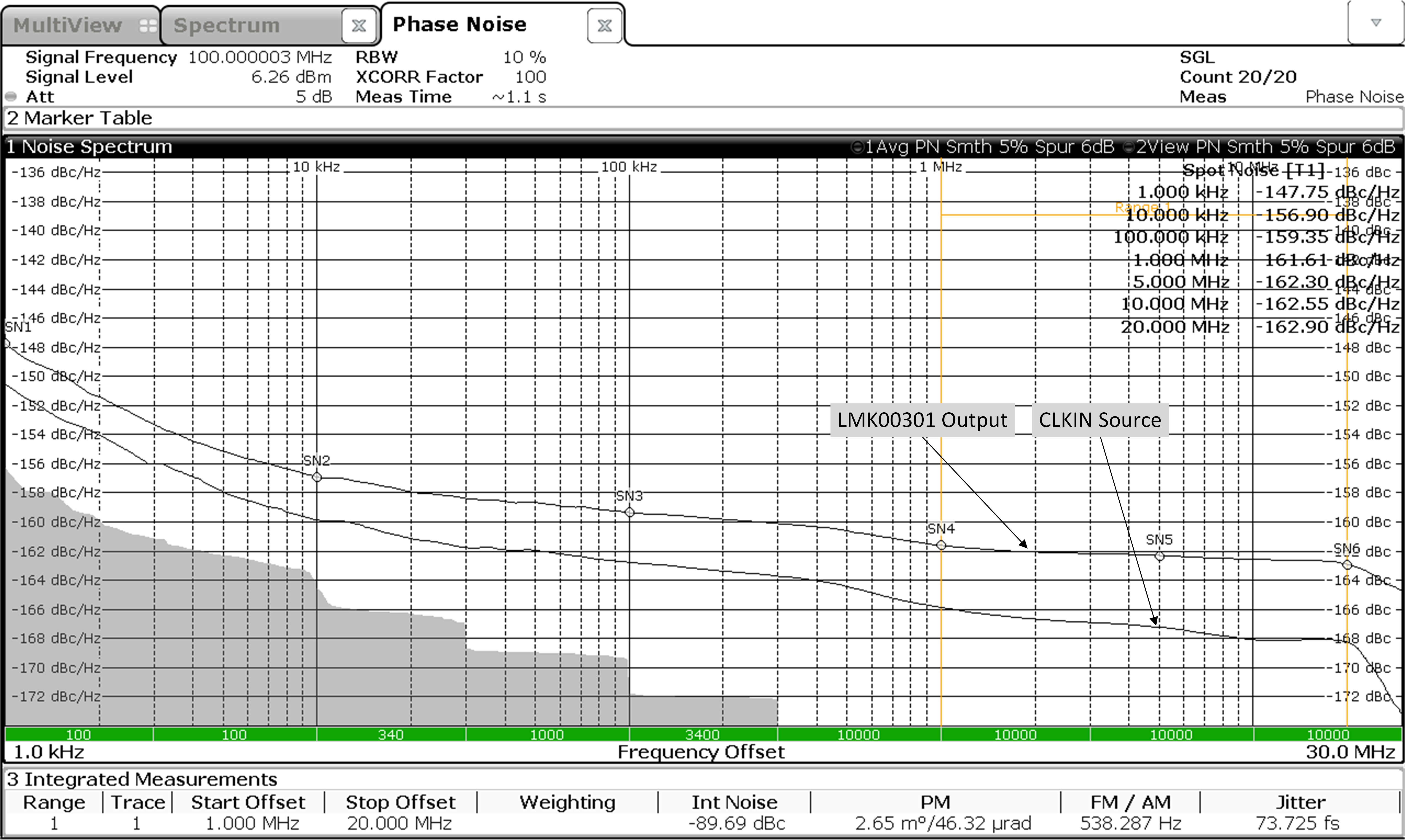
Unless otherwise specified: VCC = 3.3 V, VCCO = 3.3 V, TA = 25°C, CLKin driven differentially, input slew rate ≥ 3 V/ns. Consult Table 7-1 at the end of Typical Characteristics for graph notes.
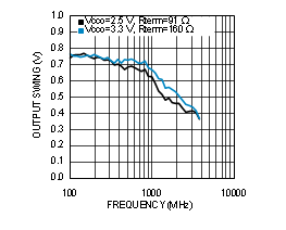
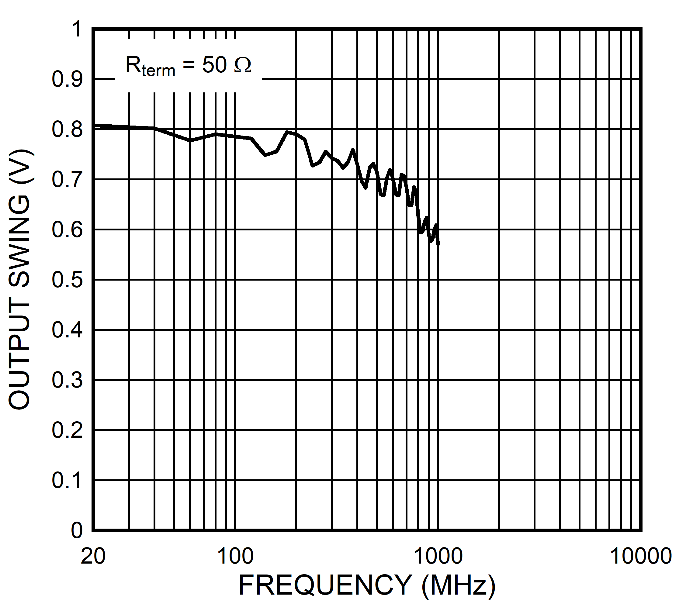
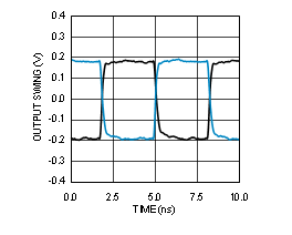
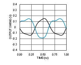
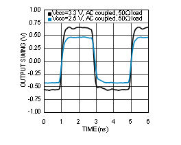
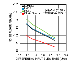
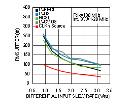
| See Note 1 in Graph Notes table | ||
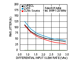
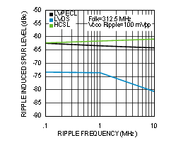
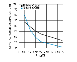
| See Notes 2 and 3 in Graph Notes table | ||
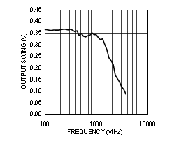
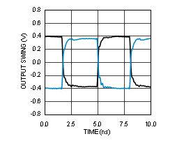
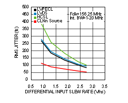
| See Note 1 in Graph Notes table | ||
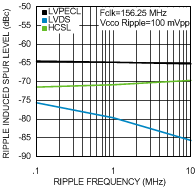
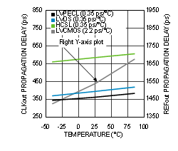
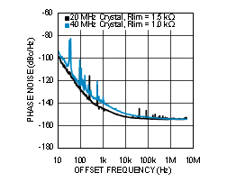
| See Notes 2 and 3 in Graph Notes table | ||

| See Note 1 in Graph Notes table | ||
| See Note 1 in Graph Notes table | ||
| See Note 1 in Graph Notes table | ||
Table 7-1 Graph Notes
| NOTE | ||||
|---|---|---|---|---|
| (1) | The typical RMS jitter values in the plots show the total output RMS jitter (JOUT) for each output buffer type and the source clock RMS jitter (JSOURCE). From these values, the Additive RMS Jitter can be calculated as: JADD = SQRT(JOUT2 – JSOURCE2). | |||
| (2) | 20 MHz crystal characteristics: Abracon ABL series, AT cut, CL = 18 pF , C0 = 4.4 pF measured (7 pF maximum), ESR = 8.5 Ω measured (40 Ω maximum), and Drive Level = 1 mW maximum (100 µW typical). | |||
| (3) | 40 MHz crystal characteristics: Abracon ABLS2 series, AT cut, CL = 18 pF , C0 = 5 pF measured (7 pF maximum), ESR = 5 Ω measured (40 Ω maximum), and Drive Level = 1 mW maximum (100 µW typical). | |||