JAJSKW2B June 2020 – June 2021 LMK05318B
PRODUCTION DATA
- 1 特長
- 2 アプリケーション
- 3 概要
- 4 Revision History
- 5 概要 (続き)
- 6 Pin Configuration and Functions
- 7 Specifications
- 8 Parameter Measurement Information
-
9 Detailed Description
- 9.1 Overview
- 9.2 Functional Block Diagram
- 9.3
Feature Description
- 9.3.1 Oscillator Input (XO_P/N)
- 9.3.2 Reference Inputs (PRIREF_P/N and SECREF_P/N)
- 9.3.3 Clock Input Interfacing and Termination
- 9.3.4 Reference Input Mux Selection
- 9.3.5 Hitless Switching
- 9.3.6 Gapped Clock Support on Reference Inputs
- 9.3.7 Input Clock and PLL Monitoring, Status, and Interrupts
- 9.3.8
PLL Relationships
- 9.3.8.1 PLL Frequency Relationships
- 9.3.8.2 Analog PLLs (APLL1, APLL2)
- 9.3.8.3 APLL Reference Paths
- 9.3.8.4 APLL Phase Frequency Detector (PFD) and Charge Pump
- 9.3.8.5 APLL Feedback Divider Paths
- 9.3.8.6 APLL Loop Filters (LF1, LF2)
- 9.3.8.7 APLL Voltage Controlled Oscillators (VCO1, VCO2)
- 9.3.8.8 APLL VCO Clock Distribution Paths (P1, P2)
- 9.3.8.9 DPLL Reference (R) Divider Paths
- 9.3.8.10 DPLL Time-to-Digital Converter (TDC)
- 9.3.8.11 DPLL Loop Filter (DLF)
- 9.3.8.12 DPLL Feedback (FB) Divider Path
- 9.3.9 Output Clock Distribution
- 9.3.10 Output Channel Muxes
- 9.3.11 Output Dividers (OD)
- 9.3.12 Clock Outputs (OUTx_P/N)
- 9.3.13 Glitchless Output Clock Start-Up
- 9.3.14 Clock Output Interfacing and Termination
- 9.3.15 Output Synchronization (SYNC)
- 9.3.16 Zero-Delay Mode (ZDM) Synchronization for 1-PPS Input and Output
- 9.4 Device Functional Modes
- 9.5 Programming
- 10Application and Implementation
- 11Power Supply Recommendations
- 12Layout
- 13Device and Documentation Support
- 14Mechanical, Packaging, and Orderable Information
パッケージ・オプション
メカニカル・データ(パッケージ|ピン)
- RGZ|48
サーマルパッド・メカニカル・データ
- RGZ|48
発注情報
9.3.1 Oscillator Input (XO_P/N)
The XO input is the reference clock for the fractional-N APLLs. The XO input determines the output frequency accuracy and stability in free-run or holdover modes.
For DPLL mode, the XO frequency must have a non-integer relationship with the VCO1 frequency so APLL1 can operate in fractional mode. For APLL-only mode, the XO frequency can have an integer or fractional relationship with the VCO1 and/or VCO2 frequencies.
In DPLL mode applications, such as SyncE and IEEE 1588, the XO input can be driven by a low-frequency TCXO, OCXO, or external traceable clock that conforms to the frequency accuracy and holdover stability required by the applicable synchronization standard. TCXO and OCXO frequencies of 12.8, 19.2, 19.44, 24, 24.576, and 30.72 MHz are commonly available and cost-effective options that allow the APLL1 to operate in fractional mode for a VCO1 frequency of 2.5 GHz.
An XO/TCXO/OCXO source with low-frequency or a high-phase jitter/noise floor will have no impact on the output jitter performance because the BAW VCO determines the jitter and phase noise over the 12-kHz to 20-MHz integration bandwidth.
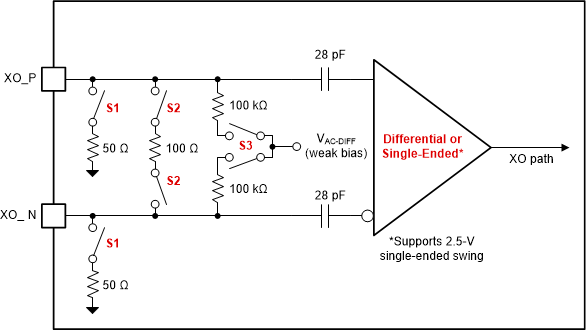
The XO input buffer has programmable input on-chip termination and AC-coupled input biasing configurations as shown in Figure 9-6. The buffered XO path also drives the input monitoring blocks.
 Figure 9-6 XO Input Buffer
Table 9-1 lists the typical XO input buffer configurations for common clock interface types.
| XO_TYPE | INPUT TYPES | INTERNAL SWITCH SETTINGS | |
|---|---|---|---|
| INTERNAL TERM. (S1, S2)(1) | INTERNAL BIAS (S3)(2) | ||
| 1h | Differential (DC-coupled or AC-coupled) | OFF | ON (1.3 V) |
| 3h | Differential (AC-coupled or DC-coupled, Internal 100-Ω) | 100 Ω | ON (1.3 V) |
| 4h | HCSL (DC-coupled, internal 50-Ω) | 50 Ω | OFF |
| 8h | LVCMOS (DC-coupled) | OFF | OFF |
| Ch | Single-ended (DC-coupled, internal 50-Ω) | 50 Ω | OFF |