JAJSP11A August 2022 – December 2022 LP5891-Q1
PRODUCTION DATA
- 1 特長
- 2 アプリケーション
- 3 概要
- 4 Revision History
- 5 概要 (続き)
- 6 Pin Configuration and Functions
- 7 Specifications
-
8 Detailed Description
- 8.1 Overview
- 8.2 Functional Block Diagram
- 8.3
Feature Description
- 8.3.1 Independent and Stackable Mode
- 8.3.2 Current Setting
- 8.3.3 Frequency Multiplier
- 8.3.4 Line Transitioning Sequence
- 8.3.5 Protections and Diagnostics
- 8.4 Device Functional Modes
- 8.5 Continuous Clock Series Interface
- 8.6 PWM Grayscale Control
- 8.7 Register Maps
- 9 Application and Implementation
- 10Device and Documentation Support
- 11Mechanical, Packaging, and Orderable Information
パッケージ・オプション
デバイスごとのパッケージ図は、PDF版データシートをご参照ください。
メカニカル・データ(パッケージ|ピン)
- RRF|76
サーマルパッド・メカニカル・データ
発注情報
8.3.1.1 Independent Mode
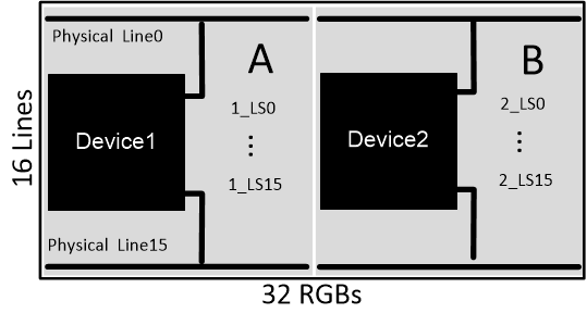
Figure 8-1 shows an implementation of a 16 × 32 RGB LED matrix using two LP5891-Q1 devices in independent mode. Each device is responsible for its own 16 ×16 RGB LED matrix, which means that all the data for section A is stored in device 1 and the data for section B is stored in device 2.
 Figure 8-1 Two Devices in Independent Mode
The unused line must be assigned to the last several lines of the device. For example, if there are only 14 scanning lines, then the two unused lines must be assigned to 1_LS14 and 1_LS15.