JAJS273D July 2003 – November 2016 MSP430FE423 , MSP430FE425 , MSP430FE427
PRODUCTION DATA.
TI MSP430™ファミリの超低消費電力マイクロコントローラは複数のデバイスで構成され、それぞれが各種のアプリケーションを対象とする異なるペリフェラルを搭載しています。このアーキテクチャは5つの低消費電力モードを持ち、携帯用測定器用途でバッテリ駆動時間を延長するよう最適化されています。このデバイスには、強力な16ビットRISC CPU、16ビット・レジスタ、およびコンスタント・ジェネレータが搭載されており、コード効率が最大限に発揮されます。デジタル制御発振器(DCO)により、デバイスは低消費電力モードからアクティブ・モードへ6µs以内にウェークアップできます。
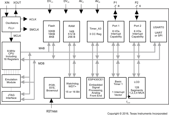
MSP430FE42xシリーズは、3つの独立した16ビットのシグマ-デルタADCと、内蔵の信号プロセッサ・コアを持つマイクロコントローラ構成であり、2線式および3線式の両方の構成で単相エネルギーを測定、計算するため使用されます。また、16ビットのタイマ、128セグメントのLCDドライブ機能、14本のI/Oピンも搭載されています。
代表的なアプリケーションは、変更を加えることのできない堅牢なメータなど、2線式および3線式の単相計測です。
型番 | パッケージ | 本体サイズ(2) |
---|---|---|
MSP430FE427IPM | LQFP (64) | 10mm×10mm |
MSP430FE425IPM | LQFP (64) | 10mm×10mm |
MSP430FE423IPM | LQFP (64) | 10mm×10mm |
Changes from October 16, 2008 to November 14, 2016
Table 3-1 summarizes the available family members.
DEVICE | FLASH (KB) |
RAM (B) |
FREQUENCY (MHz) | BSL | ESP430 | I/O | PACKAGE |
---|---|---|---|---|---|---|---|
MSP430F427 | 32 | 1K | 8 | UART | 1 | 14 | PM 64 |
MSP430F425 | 16 | 512 | 8 | UART | 1 | 14 | PM 64 |
MSP430F423 | 8 | 256 | 8 | UART | 1 | 14 | PM 64 |
For information about other devices in this family of products or related products, see the following links.
Figure 4-1 shows the pinout for the 64-pin PM package.
NOTE:
TI recommends leaving all unused analog inputs open.Table 4-1 describes the signals for all device variants
SIGNAL NAME | PIN NO. | I/O | DESCRIPTION |
---|---|---|---|
DVCC | 1 | Digital supply voltage, positive terminal | |
I1+ | 2 | I | Current 1 positive analog input, internal connection to SD16 channel 0 A0+(1) |
I1− | 3 | I | Current 1 negative analog input, internal connection to SD16 channel 0 A0−(1) |
I2+ | 4 | I | Current 2 positive analog input, internal connection to SD16 channel 1 A0+(1) |
I2− | 5 | I | Current 2 negative analog input, internal connection to SD16 channel 1 A0−(1) |
V1+ | 6 | I | Voltage 1 positive analog input, internal connection to SD16 channel 2 A0+(1) |
V1− | 7 | I | Voltage 1 negative analog input, internal connection to SD16 channel 2 A0−(1) |
XIN | 8 | I | Input port for crystal oscillator XT1. Standard or watch crystals can be connected. |
XOUT | 9 | O | Output terminal of crystal oscillator XT1 |
VREF | 10 | I/O | Input for an external reference voltage, internal reference voltage output (can be used as mid-voltage) |
P2.2/STE0 | 11 | I/O | General-purpose digital I/O Slave transmit enable for USART0 in SPI mode |
S0 | 12 | O | LCD segment output 0 |
S1 | 13 | O | LCD segment output 1 |
S2 | 14 | O | LCD segment output 2 |
S3 | 15 | O | LCD segment output 3 |
S4 | 16 | O | LCD segment output 4 |
S5 | 17 | O | LCD segment output 5 |
S6 | 18 | O | LCD segment output 6 |
S7 | 19 | O | LCD segment output 7 |
S8 | 20 | O | LCD segment output 8 |
S9 | 21 | O | LCD segment output 9 |
S10 | 22 | O | LCD segment output 10 |
S11 | 23 | O | LCD segment output 11 |
S12 | 24 | O | LCD segment output 12 |
S13 | 25 | O | LCD segment output 13 |
S14 | 26 | O | LCD segment output 14 |
S15 | 27 | O | LCD segment output 15 |
S16 | 28 | O | LCD segment output 16 |
S17 | 29 | O | LCD segment output 17 |
S18 | 30 | O | LCD segment output 18 |
S19 | 31 | O | LCD segment output 19 |
S20 | 32 | O | LCD segment output 20 |
S21 | 33 | O | LCD segment output 21 |
S22 | 34 | O | LCD segment output 22 |
S23 | 35 | O | LCD segment output 23 |
COM0 | 36 | O | Common output, COM0−COM3 are used for LCD backplanes. |
COM1 | 37 | O | Common output, COM0−COM3 are used for LCD backplanes. |
COM2 | 38 | O | Common output, COM0−COM3 are used for LCD backplanes. |
COM3 | 39 | O | Common output, COM0−COM3 are used for LCD backplanes. |
R03 | 40 | I | Input port of fourth positive (lowest) analog LCD level (V5) |
R13 | 41 | I | Input port of third most positive analog LCD level (V4 or V3) |
R23 | 42 | I | Input port of second most positive analog LCD level (V2) |
R33 | 43 | O | Output port of most positive analog LCD level (V1) |
P2.1/UCLK0/S24 | 44 | I/O | General-purpose digital I/O External clock input for USART0 in UART or SPI mode, or LCD segment output 24(2) |
P2.0/TA2/S25 | 45 | I/O | General-purpose digital I/O Timer_A Capture: CCI2A input, Compare: Out2 output LCD segment output 25(2) |
P1.7/SOMI0/S26 | 46 | I/O | General-purpose digital I/O Slave out/master in for USART0 in SPI mode LCD segment output 26(2) |
P1.6/SIMO0/S27 | 47 | I/O | General-purpose digital I/O Slave in/master out for USART0 in SPI mode LCD segment output 27(2) |
P1.5/TACLK/ACLK/S28 | 48 | I/O | General-purpose digital I/O Timer_A and SD16 clock signal TACLK input ACLK output (divided by 1, 2, 4, or 8) LCD segment output 28(2) |
P1.4/S29 | 49 | I/O | General-purpose digital I/O LCD segment output 29(2) |
P1.3/SVSOUT/S30 | 50 | I/O | General-purpose digital I/O SVS: output of SVS comparator LCD segment output 30(2) |
P1.2/TA1/S31 | 51 | I/O | General-purpose digital I/O Timer_A, Capture: CCI1A, CCI1B input, Compare: Out1 output LCD segment output 31(2) |
P1.1/TA0/MCLK | 52 | I/O | General-purpose digital I/O Timer_A, Capture: CCI0B input. Note: TA0 is only an input on this pin. MCLK output BSL receive |
P1.0/TA0 | 53 | I/O | General-purpose digital I/O Timer_A, Capture: CCI0A input, Compare: Out0 output BSL transmit |
TDO/TDI | 54 | I/O | Test data output port, TDO/TDI data output or programming data input terminal |
TDI/TCLK | 55 | I | Test data input or test clock input. The device protection fuse is connected to TDI. |
TMS | 56 | I | Test mode select. TMS is used as an input port for device programming and test. |
TCK | 57 | I | Test clock. TCK is the clock input port for device programming and test. |
RST/NMI | 58 | I | Reset input or nonmaskable interrupt input port |
P2.5/URXD0 | 59 | I/O | General-purpose digital I/O Receive data in for USART0 in UART mode |
P2.4/UTXD0 | 60 | I/O | General-purpose digital I/O Transmit data out for USART0 in UART mode |
P2.3/SVSIN | 61 | I/O | General-purpose digital I/O Analog input to brownout, supply voltage supervisor |
AVSS | 62 | Analog supply voltage, negative terminal. Supplies SD16, SVS, brownout, oscillator, and LCD resistive divider circuitry. | |
DVSS | 63 | Digital supply voltage, negative terminal | |
AVCC | 64 | Analog supply voltage, positive terminal. Supplies SD16, SVS, brownout, oscillator, and LCD resistive divider circuitry. Do not power up before DVCC. |
MIN | MAX | UNIT | |||
---|---|---|---|---|---|
Voltage applied at VCC to VSS | –0.3 | 4.1 | V | ||
Voltage applied to any pin(2) | –0.3 | VCC + 0.3 | V | ||
Diode current at any device terminal | ±2 | mA | |||
Storage temperature range, Tstg | Unprogrammed device | –55 | 150 | °C | |
Programmed device | –40 | 85 |
VALUE | UNIT | |||
---|---|---|---|---|
V(ESD) | Electrostatic discharge | Human-body model (HBM), per ANSI/ESDA/JEDEC JS-001(1) | ±1000 | V |
Charged-device model (CDM), per JEDEC specification JESD22-C101(2) | ±250 |
MIN | NOM | MAX | UNIT | ||||
---|---|---|---|---|---|---|---|
VCC | Supply voltage during program execution(1) (AVCC = DVCC = VCC) | ESP430 and SD16 disabled | 1.8 | 3.6 | V | ||
SVS enabled, PORON = 1(2), ESP430 and SD16 disabled | 2.0 | 3.6 | |||||
ESP430 or SD16 enabled or during programming of flash memory | 2.7 | 3.6 | |||||
VSS | Supply voltage (AVSS = DVSS = VSS) | 0 | 0 | V | |||
TA | Operating free-air temperature range | –40 | 85 | °C | |||
f(LFXT1) | LFXT1 crystal frequency(3) | LF selected, XTS_FLL = 0 | Watch crystal | 32.768 | kHz | ||
XT1 selected, XTS_FLL = 1 | Ceramic resonator | 450 | 8000 | ||||
XT1 selected, XTS_FLL = 1 | Crystal | 1000 | 8000 | ||||
f(System) | Processor frequency (signal MCLK)(4) (also see Figure 5-1) | VCC = 2.7 V | DC | 8.4 | MHz | ||
VCC = 3.6 V | DC | 8.4 |
PARAMETER | TA | VCC | MIN | TYP | MAX | UNIT | |
---|---|---|---|---|---|---|---|
I(AM) | Active mode (AM) f(MCLK) = f(SMCLK) = f(DCO) = 1 MHz, f(ACLK) = 32768 Hz, XTS_FLL = 0, program executes in flash |
–40°C to 85°C | 3 V | 400 | 500 | µA | |
I(LPM0) | Low-power mode 0 or 1 (LPM0 or LPM1)(2)
f(MCLK) = f(SMCLK) = f(DCO) = 1 MHz, f(ACLK) = 32768 Hz, XTS_FLL = 0, FN_8 = FN_4 = FN_3 = FN_2 = 0 |
–40°C to 85°C | 3 V | 130 | 150 | µA | |
I(LPM2) | Low-power mode 2 (LPM2)(2) | –40°C to 85°C | 3 V | 10 | 22 | µA | |
I(LPM3) | Low-power mode 3 (LPM3) (2) | –40°C | 3 V | 1.5 | 2.0 | µA | |
25°C | 1.6 | 2.1 | |||||
60°C | 1.7 | 2.2 | |||||
85°C | 2.0 | 3.5 | |||||
I(LPM4) | Low-power mode 4 (LPM4)(2) | –40°C | 3 V | 0.1 | 0.5 | µA | |
25°C | 0.1 | 0.5 | |||||
85°C | 0.8 | 2.5 |
Current consumption of active mode versus system frequency:
I(AM) = I(AM) [1 MHz] × f(System) [MHz]
Current consumption of active mode versus supply voltage:
I(AM) = I(AM) [3 V] + 170 µA/V × (VCC – 3 V)
PARAMETER | VALUE | UNIT | |
---|---|---|---|
RθJA | Junction-to-ambient thermal resistance, still air(1) | 55.7 | °C/W |
RθJC(TOP) | Junction-to-case (top) thermal resistance(2) | 16.7 | °C/W |
RθJB | Junction-to-board thermal resistance(3) | 27.1 | °C/W |
ΨJB | Junction-to-board thermal characterization parameter | 26.8 | °C/W |
ΨJT | Junction-to-top thermal characterization parameter | 0.8 | °C/W |
PARAMETER | VCC | MIN | MAX | UNIT | |
---|---|---|---|---|---|
VIT+ | Positive-going input threshold voltage | 3 V | 1.5 | 1.98 | V |
VIT- | Negative-going input threshold voltage | 3 V | 0.9 | 1.3 | V |
Vhys | Input voltage hysteresis (VIT+ - VIT- ) | 3 V | 0.45 | 1 | V |
PARAMETER | TEST CONDITIONS | VCC | MIN | MAX | UNIT | |
---|---|---|---|---|---|---|
t(int) | External interrupt timing | Port P1, P2: P1.x to P2.x, external trigger signal for the interrupt flag(1) | 3 V | 1.5 | cycle | |
50 | ns | |||||
t(cap) | Timer_A capture timing | TAx | 3 V | 50 | ns | |
f(TAext) | Timer_A clock frequency externally applied to pin | TAxCLK, INCLK t(H) = t(L) | 3 V | 10 | MHz | |
f(TAint) | Timer_A clock frequency | SMCLK or ACLK signal selected | 3 V | 10 | MHz |
PARAMETER | TEST CONDITIONS | VCC | MIN | MAX | UNIT | |
---|---|---|---|---|---|---|
Ilkg(P1.x) | Leakage current, Port P1.x | Port 1: V(P1.x) (2) | 3 V | ±50 | nA | |
Ilkg(P2.x) | Leakage current, Port P2.x | Port 2: V(P2.x) (2) | 3 V | ±50 | nA |
PARAMETER | TEST CONDITIONS | VCC | MIN | MAX | UNIT | |
---|---|---|---|---|---|---|
VOH | High-level output voltage | IOH(max) = –1.5 mA(1) | 3 V | VCC – 0.25 | VCC | V |
IOH(max) = –6 mA(2) | 3 V | VCC – 0.6 | VCC | |||
VOL | Low-level output voltage | IOL(max) = 1.5 mA(1) | 3 V | VSS | VSS + 0.25 | V |
IOL(max) = 6 mA(2) | 3 V | VSS | VSS + 0.6 |
PARAMETER | TEST CONDITIONS | MIN | TYP | MAX | UNIT | ||
---|---|---|---|---|---|---|---|
f(Px.y) | Output frequency (1 ≤ × ≤ 2, 0 ≤ y ≤ 7) |
CL = 20 F, IL = ±1.5 mA, VCC = 3 V | DC | 12 | MHz | ||
f(ACLK), | P1.1/TA0/MCLK, P1.5/TACLK/ACLK/S28 |
CL = 20 pF, VCC = 3 V | 12 | MHz | |||
f(MCLK), | |||||||
f(SMCLK) | |||||||
t(Xdc) | Duty cycle of output frequency | P1.5/TACLK/ACLK/S28, CL = 20 pF, VCC = 3 V |
fACLK = fLFXT1 = fXT1 | 40% | 60% | ||
fACLK = fLFXT1 = fLF | 30% | 70% | |||||
fACLK = fLFXT1 | 50% | ||||||
P1.1/TA0/MCLK, CL = 20 pF, VCC = 3 V, fMCLK = fDCOCLK |
50% – 15 ns | 50% | 50% + 15 ns |
Figure 5-2 through Figure 5-5 show the typical output currents of Ports P1 and P2. One output loaded at a time.
PARAMETER | TEST CONDITIONS | MIN | MAX | UNIT | ||
---|---|---|---|---|---|---|
td(LPM3) | Delay time | f = 1 MHz | VCC = 3 V | 6 | µs | |
f = 2 MHz | 6 | |||||
f = 3 MHz | 6 |
PARAMETER | TEST CONDITIONS | MIN | MAX | UNIT | ||
---|---|---|---|---|---|---|
VRAMh | CPU halted(1) | 1.6 | V |
PARAMETER | TEST CONDITIONS | MIN | TYP | MAX | UNIT | ||
---|---|---|---|---|---|---|---|
V(33) | Analog voltage | Voltage at R33 | VCC = 3 V | 2.5 | VCC + 0.2 | V | |
V(23) | Voltage at R23 | [V(33) – V(03)] × 2/3 + V(03) | |||||
V(13) | Voltage at R13 | [V(33) – V(03)] × 1/3 + V(03) | |||||
V(33) – V(03) | Voltage at R33 to R03 | 2.5 | VCC + 0.2 | ||||
I(R03) | Input leakage | R03 = VSS | No load at all segment and common lines, VCC = 3 V |
±20 | nA | ||
I(R13) | R13 = VCC / 3 | ±20 | |||||
I(R23) | R23 = 2 × VCC / 3 | ±20 | |||||
V(Sxx0) | Segment line voltage | I(Sxx) = –3 µA, VCC = 3 V | V(03) | V(03) – 0.1 | V | ||
V(Sxx1) | V(13) | V(13) – 0.1 | |||||
V(Sxx2) | V(23) | V(23) – 0.1 | |||||
V(Sxx3) | V(33) | V(33) + 0.1 |
PARAMETER | TEST CONDITIONS | MIN | TYP | MAX | UNIT | |
---|---|---|---|---|---|---|
t(τ) | USART0 deglitch time | VCC = 3 V, SYNC = 0, UART mode | 150 | 280 | 500 | ns |
PARAMETER | TEST CONDITIONS | MIN | TYP | MAX | UNIT | |
---|---|---|---|---|---|---|
td(BOR) | Brownout(2) | 2000 | µs | |||
VCC(start) | dVCC/dt ≤ 3 V/s (see Figure 5-6) | 0.7 × V(B_IT– ) | V | |||
V(B_IT–) | dVCC/dt ≤ 3 V/s (see Figure 5-6 through Figure 5-8) | 1.71 | V | |||
Vhys(B_IT–) | dVCC/dt ≤ 3 V/s (see Figure 5-6) | 70 | 130 | 180 | mV | |
t(reset) | Pulse duration needed at RST/NMI pin to accept reset internally, VCC = 3 V | 2 | µs |
PARAMETER | TEST CONDITIONS | MIN | TYP | MAX | UNIT | |
---|---|---|---|---|---|---|
t(SVSR) | dVCC/dt > 30 V/ms (see Figure 5-9) | 5 | 150 | µs | ||
dVCC/dt ≤ 30 V/ms | 2000 | |||||
td(SVSon) | SVS on, switch from VLD = 0 to VLD ≠ 0, VCC = 3 V | 20 | 150 | µs | ||
tsettle | VLD ≠ 0(2) | 12 | µs | |||
V(SVSstart) | VLD ≠ 0, VCC/dt ≤ 3 V/s (see Figure 5-9) | 1.55 | 1.7 | V | ||
Vhys(SVS_IT–) | VCC/dt ≤ 3 V/s (see Figure 5-9) | VLD = 1 | 70 | 120 | 155 | mV |
VLD = 2 to 14 | V(SVS_IT–) × 0.004 | V(SVS_IT–) × 0.008 | ||||
VCC/dt ≤ 3 V/s (see Figure 5-9), external voltage applied on P2.3 | VLD = 15 | 4.4 | 10.4 | mV | ||
V(SVS_IT–) | VCC/dt ≤ 3 V/s (see Figure 5-9) | VLD = 1 | 1.8 | 1.9 | 2.05 | V |
VLD = 2 | 1.94 | 2.1 | 2.25 | |||
VLD = 3 | 2.05 | 2.2 | 2.37 | |||
VLD = 4 | 2.14 | 2.3 | 2.48 | |||
VLD = 5 | 2.24 | 2.4 | 2.6 | |||
VLD = 6 | 2.33 | 2.5 | 2.71 | |||
VLD = 7 | 2.46 | 2.65 | 2.86 | |||
VLD = 8 | 2.58 | 2.8 | 3 | |||
VLD = 9 | 2.69 | 2.9 | 3.13 | |||
VLD = 10 | 2.83 | 3.05 | 3.29 | |||
VLD = 11 | 2.94 | 3.2 | 3.42 | |||
VLD = 12 | 3.11 | 3.35 | 3.61(1) | |||
VLD = 13 | 3.24 | 3.5 | 3.76(1) | |||
VLD = 14 | 3.43 | 3.7(1) | 3.99(1) | |||
VCC/dt ≤ 3 V/s (see Figure 5-9), external voltage applied on P2.3 | VLD = 15 | 1.1 | 1.2 | 1.3 | ||
ICC(SVS)(3) | VLD ≠ 0, VCC = 2.2 V or 3 V | 10 | 15 | µA |
PARAMETER | TEST CONDITIONS | VCC | MIN | TYP | MAX | UNIT |
---|---|---|---|---|---|---|
f(DCOCLK) | N(DCO) = 01Eh, FN_8 = FN_4 = FN_3 = FN_2 = 0, D = 2, DCOPLUS = 0, fCrystal = 32.768 kHz | 3 V | 1 | MHz | ||
f(DCO = 2) | FN_8 = FN_4 = FN_3 = FN_2 = 0, DCOPLUS = 1 | 3 V | 0.3 | 0.7 | 1.3 | MHz |
f(DCO = 27) | FN_8 = FN_4 = FN_3 = FN_2 = 0, DCOPLUS = 1 | 3 V | 2.7 | 6.1 | 11.3 | MHz |
f(DCO = 2) | FN_8 = FN_4 = FN_3 = FN_2 = 1, DCOPLUS = 1 | 3 V | 0.8 | 1.5 | 2.5 | MHz |
f(DCO = 27) | FN_8 = FN_4 = FN_3 = FN_2 = 1, DCOPLUS = 1 | 3 V | 6.5 | 12.1 | 20 | MHz |
f(DCO = 2) | FN_8 = FN_4 = 0, FN_3 = 1, FN_2 = x, DCOPLUS = 1 | 3 V | 1.3 | 2.2 | 3.5 | MHz |
f(DCO = 27) | FN_8 = FN_4 = 0, FN_3 = 1, FN_2 = x, DCOPLUS = 1 | 3 V | 10.3 | 17.9 | 28.5 | MHz |
f(DCO = 2) | FN_8 = 0, FN_4 = 1, FN_3 = FN_2 = x, DCOPLUS = 1 | 3 V | 2.1 | 3.4 | 5.2 | MHz |
f(DCO = 27) | FN_8 = 0, FN_4 = 1, FN_3 = FN_2 = x, DCOPLUS = 1 | 3 V | 16 | 26.6 | 41 | MHz |
f(DCO = 2) | FN_8 = 1, FN_4 = 1 = FN_3 = FN_2 = x, DCOPLUS = 1 | 3 V | 4.2 | 6.3 | 9.2 | MHz |
f(DCO = 27) | FN_8 = 1, FN_4 = 1 = FN_3 = FN_2 = x, DCOPLUS = 1 | 3 V | 30 | 46 | 70 | MHz |
Sn | Step size (ratio) between adjacent DCO taps: Sn = fDCO(Tap n+1)/fDCO(Tap n) (see Figure 5-12 for taps 21 to 27) |
1 < TAP ≤ 20 | 1.06 | 1.11 | ||
TAP = 27 | 1.07 | 1.17 | ||||
Dt | Temperature drift, N(DCO) = 01Eh, FN_8 = FN_4 = FN_3 = FN_2 = 0, D = 2, DCOPLUS = 0 | 3 V | –0.2 | –0.3 | –0.4 | %/°C |
DV | Drift with VCC variation, N(DCO) = 01Eh, FN_8 = FN_4 = FN_3 = FN_2 = 0, D = 2, DCOPLUS = 0 | 0 | 5 | 15 | %/V |
PARAMETER | TEST CONDITIONS | VCC | MIN | TYP | MAX | UNIT | |
---|---|---|---|---|---|---|---|
CXIN | Integrated input capacitance(4) | OSCCAPx = 0h | 3 V | 0 | pF | ||
OSCCAPx = 1h | 10 | ||||||
OSCCAPx = 2h | 14 | ||||||
OSCCAPx = 3h | 18 | ||||||
CXOUT | Integrated output capacitance(4) | OSCCAPx = 0h | 3 V | 0 | pF | ||
OSCCAPx = 1h | 10 | ||||||
OSCCAPx = 2h | 14 | ||||||
OSCCAPx = 3h | 18 | ||||||
VIL | Input levels at XIN(3) | 2.2 V, 3 V | VSS | 0.2 × VCC | V | ||
VIH | 0.8 × VCC | VCC |
PARAMETER | TEST CONDITIONS | VCC | MIN | TYP | MAX | UNIT | ||
---|---|---|---|---|---|---|---|---|
AVCC | Analog supply voltage | AVCC = DVCC, AVSS = DVSS = 0 V | 2.7 | 3.6 | V | |||
IESP430CE1 | Total digital and analog supply current when ESP430 and SD16 active (IAVCC + IDVCC) | SD16LP = 0, fMCLK = 4 MHz, fSD16 = fMCLK / 4, SD16REFON = 1, SD16VMIDON = 0 |
GAIN(V): 1, GAIN(I1): 1, I2: off | 3 V | 2.0 | 2.6 | mA | |
GAIN(V): 1, GAIN(I1): 32, I2: off | 2.4 | 3.3 | ||||||
GAIN(V): 1, GAIN(I1): 1, GAIN(I2): 1 | 2.7 | 3.6 | ||||||
GAIN(V): 1, GAIN(I1): 32, GAIN(I2): 32 | 3.4 | 4.9 | ||||||
SD16LP = 1, fMCLK = 2 MHz, fSD16 = fMCLK / 4, SD16REFON = 1, SD16VMIDON = 0 |
GAIN(V): 1, GAIN(I1): 1, I2: off | 1.5 | 2.1 | |||||
GAIN(V): 1, GAIN(I1): 32, I2: off | 1.6 | 2.1 | ||||||
GAIN(V): 1, GAIN(I1): 1, GAIN(I2): 1 | 2.1 | 2.8 | ||||||
GAIN(V): 1, GAIN(I1): 32, GAIN(I2): 32 | 2.2 | 3.0 | ||||||
ISD16 | Analog supply current: 1 active SD16 channel including internal reference (ESP430 disabled) | SD16LP = 0, fSD16 = 1 MHz, SD16OSR = 256 |
GAIN: 1, 2 | 3 V | 650 | 950 | µA | |
GAIN: 4, 8, 16 | 730 | 1100 | ||||||
GAIN: 32 | 1050 | 1550 | ||||||
SD16LP = 1, fSD16 = 0.5 MHz, SD16OSR = 256 |
GAIN: 1 | 620 | 930 | |||||
GAIN: 32 | 700 | 1060 | ||||||
fMAINS | Mains frequency range | 33 | 80 | Hz | ||||
fSD16 | Analog front-end input clock frequency | SD16LP = 0 (low-power mode disabled) | 1 | MHz | ||||
SD16LP = 1 (low-power mode enabled) | 0.5 |
PARAMETER | TEST CONDITIONS | VCC | MIN | TYP | MAX | UNIT | |
---|---|---|---|---|---|---|---|
VID | Differential input voltage range for specified performance(2) | SD16GAINx = 1, SD16REFON = 1 | ±500 | mV | |||
SD16GAINx = 2, SD16REFON = 1 | ±250 | ||||||
SD16GAINx = 4, SD16REFON = 1 | ±125 | ||||||
SD16GAINx = 8, SD16REFON = 1 | ±62 | ||||||
SD16GAINx = 16, SD16REFON = 1 | ±31 | ||||||
SD16GAINx = 32, SD16REFON = 1 | ±15 | ||||||
ZI | Input impedance (one input pin to AVSS) |
fSD16 = 1 MHz, SD16GAINx = 1 | 3 V | 200 | kΩ | ||
fSD16 = 1 MHz, SD16GAINx = 32 | 75 | ||||||
ZID | Differential input impedance (IN+ to IN−) |
fSD16 = 1 MHz, SD16GAINx = 1 | 3 V | 300 | 400 | kΩ | |
fSD16 = 1 MHz, SD16GAINx = 32 | 100 | 150 | |||||
VI | Absolute input voltage range | AVSS – 1 | AVCC | V | |||
VIC | Common-mode input voltage range | AVSS – 1 | AVCC | V |
PARAMETER | TEST CONDITIONS | VCC | MIN | TYP | MAX | UNIT | ||
---|---|---|---|---|---|---|---|---|
SINAD | Signal-to-noise + distortion ratio | SD16GAINx = 1, signal amplitude = 500 mV | fIN = 50 Hz or 100 Hz | 3 V | 83.5 | 85 | dB | |
SD16GAINx = 2, signal amplitude = 250 mV | 81.5 | 84 | ||||||
SD16GAINx = 4, signal amplitude = 125 mV | 76 | 79.5 | ||||||
SD16GAINx = 8, signal amplitude = 62 mV | 73 | 76.5 | ||||||
SD16GAINx = 16, signal amplitude = 31 mV | 69 | 73 | ||||||
SD16GAINx = 32, signal amplitude = 15 mV | 62 | 69 | ||||||
G | Nominal gain | SD16GAINx = 1 | 3 V | 0.97 | 1.00 | 1.02 | ||
SD16GAINx = 2 | 1.90 | 1.96 | 2.02 | |||||
SD16GAINx = 4 | 3.76 | 3.86 | 3.96 | |||||
SD16GAINx = 8 | 7.36 | 7.62 | 7.84 | |||||
SD16GAINx = 16 | 14.56 | 15.04 | 15.52 | |||||
SD16GAINx = 32 | 27.20 | 28.35 | 29.76 | |||||
EOS | Offset error | SD16GAINx = 1 | 3 V | ±0.2 | %FSR | |||
SD16GAINx = 32 | ±1.5 | |||||||
dEOS/dT | Offset error temperature coefficient | SD16GAINx = 1 | 3 V | ±4 | ±20 | ppm FSR/°C | ||
SD16GAINx = 32 | ±20 | ±100 | ||||||
CMRR | Common-mode rejection ratio | SD16GAINx = 1, Common-mode input signal: VID = 500 mV, fIN = 50 Hz or 100 Hz |
3 V | >90 | dB | |||
SD16GAINx = 32, Common-mode input signal: VID = 16 mV, fIN = 50 Hz or 100 Hz |
>75 | |||||||
AC PSRR | AC power-supply rejection ratio | SD16GAINx = 1, VCC = 3 V ±100 mV, fVCC = 50 Hz | 3 V | >80 | dB | |||
XT | Crosstalk | 3 V | <–100 | dB |
PARAMETER | TEST CONDITIONS | VCC | MIN | TYP | MAX | UNIT | |
---|---|---|---|---|---|---|---|
TCSensor | Sensor temperature coefficient | 1.18 | 1.32 | 1.46 | mV/K | ||
VOffset,sensor | Sensor offset voltage | –100 | 100 | mV | |||
VSensor | Sensor output voltage(2) | Temperature sensor voltage at TA = 85°C | 3 V | 435 | 475 | 515 | mV |
Temperature sensor voltage at TA = 25°C | 355 | 395 | 435 | ||||
Temperature sensor voltage at TA = 0°C | 320 | 360 | 400 |
PARAMETER | TEST CONDITIONS | VCC | MIN | TYP | MAX | UNIT | |
---|---|---|---|---|---|---|---|
VREF | Internal reference voltage | SD16REFON = 1, SD16VMIDON = 0 | 3 V | 1.14 | 1.20 | 1.26 | V |
IREF | Reference supply current | SD16REFON = 1, SD16VMIDON = 0 | 3 V | 175 | 260 | µA | |
TC | Temperature coefficient | SD16REFON = 1, SD16VMIDON = 0(1) | 3 V | 20 | 50 | ppm/K | |
CREF | VREF load capacitance | SD16REFON = 1 SD16VMIDON = 0(2) | 100 | nF | |||
ILOAD | VREF(I) maximum load current | SD16REFON = 0, SD16VMIDON = 0 | 3 V | ±200 | nA | ||
tON | Turnon time | SD16REFON = 0 → 1, SD16VMIDON = 0, CREF = 100 nF |
3 V | 5 | ms | ||
DC PSR | DC power supply rejection, ΔVREF/ΔVCC | SD16REFON = 1, SD16VMIDON = 0, VCC = 2.5 V to 3.6 V |
200 | µV/V |
PARAMETER | TEST CONDITIONS | VCC | MIN | TYP | MAX | UNIT | |
---|---|---|---|---|---|---|---|
VREF,BUF | Reference buffer output voltage | SD16REFON = 1, SD16VMIDON = 1 | 3 V | 1.2 | V | ||
IREF,BUF | Reference supply and reference output buffer quiescent current | SD16REFON = 1, SD16VMIDON = 1 | 3 V | 385 | 600 | A | |
CREF(O) | Required load capacitance on VREF | SD16REFON = 1, SD16VMIDON = 1 | 470 | nF | |||
ILOAD,Max | Maximum load current on VREF | SD16REFON = 1, SD16VMIDON = 1 | 3 V | ±1 | mA | ||
Maximum voltage variation versus load current | |ILOAD| = 0 to 1 mA | 3 V | –15 | +15 | mV | ||
tON | Turnon time | SD16REFON = 0 → 1, SD16VMIDON = 0, CREF = 100 nF |
3 V | 100 | µs |
PARAMETER | TEST CONDITIONS | VCC | MIN | TYP | MAX | UNIT | |
---|---|---|---|---|---|---|---|
VREF(I) | Input voltage | SD16REFON = 0 | 3 V | 1.0 | 1.25 | 1.5 | V |
IREF(I) | Input current | SD16REFON = 0 | 3 V | 50 | nA |
PARAMETER | TEST CONDITIONS | VCC | TYP | UNIT | |
---|---|---|---|---|---|
Maximum error(2)(3) | I = 0.05 × IB, V = VN, PF = 1.0 | V1 SD16GAINx = 1, I1 SD16GAINx = 1, See Figure 5-14, R1 = 0 Ω, RB = 12.4 Ω |
3 V | ±0.17% | |
I = 0.1 × IB to IMAX, V = VN, PF = 1.0 | ±0.18% | ||||
I = 0.1 × IB, V = VN, PF = 0.5 lagging | ±0.19% | ||||
I = 0.2 × IB to IMAX, V = VN, PF = 0.5 lagging | ±0.27% | ||||
I = 0.1 × IB, V = VN, PF = 0.8 leading | ±0.15% | ||||
I = 0.2 × IB to IMAX, V = VN, PF = 0.8 leading | ±0.24% | ||||
I = 0.2 × IB to IMAX, V = VN, PF = 0.25 lagging | ±0.38% |
PARAMETER | TEST CONDITIONS | VCC | TYP | UNIT | |
---|---|---|---|---|---|
Maximum error(2)(3) | I = 0.05 × IB, V = VN, PF = 1.0 | V1 SD16GAINx = 1, I1 SD16GAINx = 32, See Figure 5-15, Rshunt = 0.2 mΩ |
3 V | ±0.11% | |
I = 0.1 × IB to IMAX, V = VN, PF = 1.0 | ±0.18% | ||||
I = 0.1 × IB, V = VN, PF = 0.5 lagging | ±0.45% | ||||
I = 0.2 × IB to IMAX, V = VN, PF = 0.5 lagging | ±0.33% | ||||
I = 0.1 × IB, V = VN, PF = 0.8 leading | ±0.10% | ||||
I = 0.2 × IB to IMAX, V = VN, PF = 0.8 leading | ±0.18% | ||||
I = 0.2 × IB to IMAX, V = VN, PF = 0.25 lagging | ±0.51% |
Results corrected for typical phase error of CT used (−40°C to 25°C: −0.7°; 25°C to 85°C: +0.5°). See Figure 5-14 for test circuitry: CT part number = T60404-E4624-X101 (Vacuumschmelze), R1 = 0 Ω, RB = 12.4 Ω
Results corrected for typical phase error of CT used (−40°C to 25°C: −0.7°; 25°C to 85°C: +0.5°). See Figure 5-14 for test circuitry: CT part number = T60404-E4624-X101 (Vacuumschmelze), R1 = 9.36 Ω, RB = 3.16 Ω
See Figure 5-15 for test circuitry: shunt part number = A-H2-R005-F1-K2-0.1 (Isabellenhütte Heusler GmbH KG)
See Figure 5-15 for test circuitry: shunt part number = BVO-M-R0002-5.0 (Isabellenhütte Heusler GmbH KG)
PARAMETER | TEST CONDITIONS | VCC | MIN | TYP | MAX | UNIT | |
---|---|---|---|---|---|---|---|
VCC(PGM/ ERASE) | Program and erase supply voltage | 2.7 | 3.6 | V | |||
fFTG | Flash timing generator frequency | 257 | 476 | kHz | |||
IPGM | Supply current from DVCC during program | 2.7 V, 3.6 V | 3 | 5 | mA | ||
IERASE | Supply current from DVCC during erase | 2.7 V, 3.6 V | 3 | 7 | mA | ||
tCPT | Cumulative program time | See (1) | 2.7 V, 3.6 V | 10 | ms | ||
tCMErase | Cumulative mass erase time | See (2) | 2.7 V, 3.6 V | 200 | ms | ||
Program and erase endurance | 104 | 105 | cycles | ||||
tRetention | Data retention duration | TJ = 25°C | 100 | years | |||
tWord | Word or byte program time | See (3) | 35 | tFTG | |||
tBlock, 0 | Block program time for first byte or word | 30 | |||||
tBlock, 1–63 | Block program time for each additional byte or word | 21 | |||||
tBlock, End | Block program end-sequence wait time | 6 | |||||
tMass Erase | Mass erase time | 5297 | |||||
tSeg Erase | Segment erase time | 4819 |
PARAMETER | TEST CONDITIONS | VCC | MIN | TYP | MAX | UNIT | |
---|---|---|---|---|---|---|---|
fTCK | TCK input frequency | See (1) | 2.2 V | 0 | 5 | MHz | |
3V | 0 | 10 | |||||
RInternal | Internal pullup resistance on TMS, TCK, TDI/TCLK | See (2) | 2.2 V, 3 V | 25 | 60 | 90 | kΩ |
PARAMETER | TEST CONDITIONS | MIN | MAX | UNIT | |
---|---|---|---|---|---|
VCC(FB) | Supply voltage during fuse-blow condition | TA = 25°C | 2.5 | V | |
VFB | Voltage level on TDI/TCLK for fuse-blow | 6 | 7 | V | |
IFB | Supply current into TDI/TCLK during fuse blow | 100 | mA | ||
tFB | Time to blow fuse | 1 | ms |
The MSP430 CPU has a 16-bit RISC architecture that is highly transparent to the application. All operations, other than program-flow instructions, are performed as register operations in conjunction with seven addressing modes for source operand and four addressing modes for destination operand.
The CPU is integrated with 16 registers that provide reduced instruction execution time. The register-to-register operation execution time is one cycle of the CPU clock.
Four of the registers, R0 to R3, are dedicated as program counter, stack pointer, status register, and constant generator, respectively. The remaining registers are general-purpose registers (see Figure 6-1).
Peripherals are connected to the CPU using data, address, and control buses. Peripherals can be manged with all instructions.
The instruction set consists of the original 51 instructions with three formats and seven address modes. Each instruction can operate on word and byte data. Table 6-1 lists examples of the three types of instruction formats; Table 6-2 lists the address modes.
INSTRUCTION FORMAT | EXAMPLE | OPERATION | |
---|---|---|---|
Dual operands, source and destination | ADD | R4,R5 | R4 + R5 → R5 |
Single operand, destination only | CALL | R8 | PC→(TOS), R8 →PC |
Relative jump, unconditional or conditional | JNE | Jump-on-equal bit = 0 |
ADDRESS MODE | S(1) | D(1) | SYNTAX | EXAMPLE | OPERATION |
---|---|---|---|---|---|
Register | ● | ● | MOV Rs, Rd | MOV R10, R11 | R10 → R11 |
Indexed | ● | ● | MOV X(Rn), Y(Rm) | MOV 2(R5), 6(R6) | M(2+R5)→ M(6+R6) |
Symbolic (PC relative) | ● | ● | MOV EDE, TONI | M(EDE) → M(TONI) | |
Absolute | ● | ● | MOV & MEM, & TCDAT | M(MEM) → M(TCDAT) | |
Indirect | ● | MOV @Rn, Y(Rm) | MOV @R10, Tab(R6) | M(R10) → M(Tab+R6) | |
Indirect autoincrement | ● | MOV @Rn+, Rm | MOV @R10+, R11 | M(R10) → R11 R10 + 2→ R10 |
|
Immediate | ● | MOV #X, TONI | MOV #45, TONI | #45 → M(TONI) |
The MSP430FE42x has one active mode and five software-selectable low-power modes of operation. An interrupt event can wake up the device from any of the five low-power modes, service the request, and restore back to the low-power mode on return from the interrupt program.
Software can configure the following operating modes:
The interrupt vectors and the power-up starting address are in the address range 0FFFFh to 0FFE0h. The vector contains the 16-bit address of the appropriate interrupt-handler instruction sequence. Table 6-3 lists the interrupt sources, flags, and vectors.
INTERRUPT SOURCE | INTERRUPT FLAG | SYSTEM INTERRUPT | WORD ADDRESS | PRIORITY |
---|---|---|---|---|
Power up External reset Watchdog Flash memory PC out of range(4) |
WDTIFG KEYV(1) |
Reset | 0FFFEh | 15, highest |
NMI oscillator fault Flash memory access violation |
NMIIFG(1)
OFIFG(1) ACCVIFG(1) |
(Non)maskable(3)
(Non)maskable (Non)maskable |
0FFFCh | 14 |
ESP430 | MBCTL_OUTxIFG, MBCTL_INxIFG(1)(2) | Maskable | 0FFFAh | 13 |
SD16 | SD16CCTLx SD16OVIFG, SD16CCTLx SD16IFG(1)(2) |
Maskable | 0FFF8h | 12 |
0FFF6h | 11 | |||
Watchdog timer | WDTIFG | Maskable | 0FFF4h | 10 |
USART0 receive | URXIFG0 | Maskable | 0FFF2h | 9 |
USART0 transmit | UTXIFG0 | Maskable | 0FFF0h | 8 |
0FFEEh | 7 | |||
Timer_A3 | TACCR0 CCIFG(2) | Maskable | 0FFECh | 6 |
Timer_A3 | TACCR1 and TACCR2 CCIFGs, and TACTL TAIFG(1)(2) |
Maskable | 0FFEAh | 5 |
I/O port P1 (8 flags) | P1IFG.0 to P1IFG.7(1)(2) | Maskable | 0FFE8h | 4 |
0FFE6h | 3 | |||
0FFE4h | 2 | |||
I/O port P2 (8 flags) | P2IFG.0 to P2IFG.7(1)(2) | Maskable | 0FFE2h | 1 |
Basic Timer1 | BTIFG | Maskable | 0FFE0h | 0, lowest |
Most interrupt and module-enable bits are collected in the lowest address space. Special-function register bits not allocated to a functional purpose are not physically present in the device. This arrangement provides simple software access.
Legend | ||
rw | Bit can be read and written. | |
rw-0, rw-1 | Bit can be read and written. It is reset or set by PUC. | |
rw-(0), rw-(1) | Bit can be read and written. It is reset or set by POR. | |
SFR bit is not present in device. |
Figure 6-2 shows the Interrupt Enable Register 1, and Table 6-4 describes the bit fields.
7 | 6 | 5 | 4 | 3 | 2 | 1 | 0 |
UTXIE0 | URXIE0 | ACCVIE | NMIIE | OFIE | WDTIE | ||
rw-0 | rw-0 | rw-0 | rw-0 | rw-0 | rw-0 |
BIT | FIELD | TYPE | RESET | DESCRIPTION |
---|---|---|---|---|
7 | UTXIE0 | RW | 0h | USART0: UART and SPI transmit interrupt enable |
6 | URXIE0 | RW | 0h | USART0: UART and SPI receive interrupt enable |
5 | ACCVIE | RW | 0h | Flash access violation interrupt enable |
4 | NMIIE | RW | 0h | (Non)maskable interrupt enable |
1 | OFIE | RW | 0h | Oscillator fault interrupt enable |
0 | WDTIE | RW | 0h | Watchdog timer interrupt enable. Inactive if watchdog mode is selected. Active if watchdog timer is configured in interval timer mode. |
Figure 6-3 shows the Interrupt Enable Register 2, and Table 6-5 describes the bit fields.
7 | 6 | 5 | 4 | 3 | 2 | 1 | 0 |
BTIE | |||||||
rw-0 |
BIT | FIELD | TYPE | RESET | DESCRIPTION |
---|---|---|---|---|
7 | BTIE | RW | 0h | Basic Timer1 interrupt enable |
Figure 6-4 shows the Interrupt Flag Register 1, and Table 6-6 describes the bit fields.
7 | 6 | 5 | 4 | 3 | 2 | 1 | 0 |
UTXIFG0 | URXIFG0 | NMIIFG | OFIFG | WDTIFG | |||
rw-1 | rw-0 | rw-0 | rw-1 | rw-(0) |
BIT | FIELD | TYPE | RESET | DESCRIPTION |
---|---|---|---|---|
7 | UTXIFG0 | RW | 1h | USART0: UART and SPI transmit flag |
6 | URXIFG0 | RW | 0h | USART0: UART and SPI receive flag |
4 | NMIIFG | RW | 0h | Set by the RST/NMI pin |
1 | OFIFG | RW | 1h | Flag set on oscillator fault. |
0 | WDTIFG | RW | 0h | Set on watchdog timer overflow (in watchdog mode) or security key violation. Reset on VCC power on or a reset condition at the RST/NMI pin in reset mode. |
Figure 6-5 shows the Interrupt Flag Register 2, and Table 6-7 describes the bit fields.
7 | 6 | 5 | 4 | 3 | 2 | 1 | 0 |
BTIFG | |||||||
rw-0 |
BIT | FIELD | TYPE | RESET | DESCRIPTION |
---|---|---|---|---|
7 | BTIFG | RW | 0h | Basic Timer1 interrupt flag |
Figure 6-6 shows the Module Enable Register 1, and Table 6-8 describes the bit fields.
7 | 6 | 5 | 4 | 3 | 2 | 1 | 0 |
UTXE0 | URXE0 USPIE0 |
||||||
rw-0 | rw-0 |
BIT | FIELD | TYPE | RESET | DESCRIPTION |
---|---|---|---|---|
7 | UTXE0 | RW | 0h | USART0: UART mode transmit enable |
6 | URXE0 USPIE0 |
RW | 0h | USART0: UART mode receive enable USART0: SPI mode transmit and receive enable |
Module Enable Register 2 is not defined for the MSP430FE42x MCUs.
Table 6-9 summarizes the memory map of the MSP430FE42x MCUs.
MSP430FE423 | MSP430FE425 | MSP430FE427 | ||
---|---|---|---|---|
Memory | Size | 8KB | 16KB | 32KB |
Interrupt vector | Flash | 0FFFFh–0FFE0h | 0FFFFh–0FFE0h | 0FFFFh–0FFE0h |
Code memory | Flash | 0FFFFh–0E000h | 0FFFFh–0C000h | 0FFFFh–08000h |
Information memory | Size | 256 Byte | 256 Byte | 256 Byte |
010FFh–01000h | 010FFh–01000h | 010FFh–01000h | ||
Boot memory | Size | 1KB | 1KB | 1KB |
0FFFh–0C00h | 0FFFh–0C00h | 0FFFh–0C00h | ||
RAM | Size | 256 Byte | 512 Byte | 1KB |
02FFh–0200h | 03FFh–0200h | 05FFh–0200h | ||
Peripherals | 16-bit | 01FFh–0100h | 01FFh–0100h | 01FFh–0100h |
8-bit | 0FFh–010h | 0FFh–010h | 0FFh–010h | |
8-bit SFR | 0Fh–00h | 0Fh–00h | 0Fh–00h |
The MSP430 bootloader (BSL) enables users to program the flash memory or RAM using a UART serial interface. Access to the MSP430 memory through the BSL is protected by user-defined password. For complete description of the features of the BSL and its implementation, see MSP430 Programming WIth the Bootloader (BSL).
BSL FUNCTION | PM PACKAGE PINS |
---|---|
Data transmit | 53 - P1.0 |
Data receiver | 52 - P1.1 |
The flash memory (see Figure 6-7) can be programmed using the JTAG port, the bootloader, or in system by the CPU. The CPU can perform single-byte and single-word writes to the flash memory. Features of the flash memory include:
Peripherals are connected to the CPU through data, address, and control buses. Peripherals can be managed using all instructions. For complete module descriptions, see the MSP430x4xx Family User's Guide.
The clock system is supported by the FLL+ module that includes support for a 32768-Hz watch crystal oscillator, an internal digitally controlled oscillator (DCO), and a high-frequency crystal oscillator. The FLL+ clock module is designed to meet the requirements of both low system cost and low power consumption. The FLL+ features digital frequency locked loop (FLL) hardware that, in conjunction with a digital modulator, stabilizes the DCO frequency to a programmable multiple of the watch crystal frequency. The internal DCO provides a fast turnon clock source and stabilizes in less than 6 µs. The FLL+ module provides the following clock signals:
The brownout circuit provides the proper internal reset signal to the device during power on and power off. The SVS circuitry detects if the supply voltage drops below a user-selectable level and supports both supply voltage supervision (the device is automatically reset) and supply voltage monitoring (the device is not automatically reset).
The CPU begins code execution after the brownout circuit releases the device reset. However, VCC may not have ramped to VCC(min) at that time. The user must ensure that the default FLL+ settings are not changed until VCC reaches VCC(min). If desired, the SVS circuit can be used to determine when VCC reaches VCC(min).
Two I/O ports are implemented: ports P1 and P2 (only six P2 I/O signals are available on external pins).
NOTE
Six bits of port P2 (P2.0 to P2.5) are available on external pins, but all control and data bits for port P2 are implemented.
The Basic Timer1 has two independent 8-bit timers that can be cascaded to form a 16-bit timer/counter. Both timers can be read and written by software. The Basic Timer1 can be used to generate periodic interrupts and clock for the LCD module.
The LCD driver generates the segment and common signals required to drive an LCD display. The LCD controller has dedicated data memory to hold segment drive information. Common and segment signals are generated as defined by the mode. Static, 2-mux, 3-mux, and 4-mux LCDs are supported by this peripheral.
The primary function of the WDT+ module is to perform a controlled system restart after a software problem occurs. If the selected time interval expires, a system reset is generated. If the watchdog function is not needed in an application, the module can be configured as an interval timer and can generate interrupts at selected time intervals.
Timer_A3 is a 16-bit timer and counter with three capture/compare registers. Timer_A3 can support multiple capture/compares, PWM outputs, and interval timing (see Table 6-10). Timer_A3 also has extensive interrupt capabilities. Interrupts may be generated from the counter on overflow conditions and from each of the capture/compare registers.
INPUT PIN NUMBER | DEVICE INPUT SIGNAL | MODULE INPUT NAME | MODULE BLOCK | MODULE OUTPUT SIGNAL | OUTPUT PIN NUMBER |
---|---|---|---|---|---|
48 - P1.5 | TACLK | TACLK | Timer | NA | |
ACLK | ACLK | ||||
SMCLK | SMCLK | ||||
48 - P1.5 | TACLK | INCLK | |||
53 - P1.0 | TA0 | CCI0A | CCR0 | TA0 | 53 - P1.0 |
52 - P1.1 | TA0 | CCI0B | |||
DVSS | GND | ||||
DVCC | VCC | ||||
51 - P1.2 | TA1 | CCI1A | CCR1 | TA1 | 51 - P1.2 |
51 - P1.2 | TA1 | CCI1B | |||
DVSS | GND | ||||
DVCC | VCC | ||||
45 - P2.0 | TA2 | CCI2A | CCR2 | TA2 | 45 - P2.0 |
ACLK (internal) | CCI2B | ||||
DVSS | GND | ||||
DVCC | VCC |
The MSP430FE42x devices have one hardware universal synchronous/asynchronous receive transmit (USART0) peripheral module that is used for serial data communication. The USART supports synchronous SPI (3- or 4-pin) and asynchronous UART communication protocols, using double-buffered transmit and receive channels.
The ESP430CE1 module integrates a hardware multiplier, three independent 16-bit Sigma-Delta ADCs (SD16) and an embedded signal processor (ESP430). The ESP430CE1 module measures 2- or 3-wire single-phase energy and automatically calculates parameters which are made available to the MSP430 CPU. The module can be calibrated and initialized to accurately calculate energy, power factor, and other values for a wide range of metering sensor configurations.
Table 6-11 and Table 6-12 list the peripheral registers with their addresses.
MODULE | REGISTER NAME | ACRONYM | ADDRESS |
---|---|---|---|
Watchdog | Watchdog timer control | WDTCTL | 0120h |
Timer_A3 | Timer0_A interrupt vector | TA0IV | 012Eh |
Timer0_A control | TACTL0 | 0160h | |
Capture/compare control 0 | TACCTL0 | 0162h | |
Capture/compare control 1 | TACCTL1 | 0164h | |
Capture/compare control 2 | TACCTL2 | 0166h | |
Reserved | 0168h | ||
Reserved | 016Ah | ||
Reserved | 016Ch | ||
Reserved | 016Eh | ||
Timer_A counter | TA0R | 0170h | |
Capture/compare 0 | TACCR0 | 0172h | |
Capture/compare 1 | TACCR1 | 0174h | |
Capture/compare 2 | TACCR2 | 0176h | |
Reserved | 0178h | ||
Reserved | 017Ah | ||
Reserved | 017Ch | ||
Reserved | 017Eh | ||
Hardware Multiplier(1) | Sum extend | SUMEXT | 013Eh |
Result high word | RESHI | 013Ch | |
Result low word | RESLO | 013Ah | |
Second operand | OP2 | 0138h | |
Multiply signed + accumulate/operand 1 | MACS | 0136h | |
Multiply + accumulate/operand 1 | MAC | 0134h | |
Multiply signed/operand 1 | MPYS | 0132h | |
Multiply unsigned/operand 1 | MPY | 0130h | |
Flash | Flash control 3 | FCTL3 | 012Ch |
Flash control 2 | FCTL2 | 012Ah | |
Flash control 1 | FCTL1 | 0128h | |
SD16(1)
(also see Table 6-12) |
General control | SD16CTL | 0100h |
Channel 0 control | SD16CCTL0 | 0102h | |
Channel 1 control | SD16CCTL1 | 0104h | |
Channel 2 control | SD16CCTL2 | 0106h | |
Reserved | 0108h | ||
Reserved | 010Ah | ||
Reserved | 010Ch | ||
Reserved | 010Eh | ||
Interrupt vector word | SD16IV | 0110h | |
Channel 0 conversion memory | SD16MEM0 | 0112h | |
Channel 1 conversion memory | SD16MEM1 | 0114h | |
Channel 2 conversion memory | SD16MEM2 | 0116h | |
Reserved | 0118h | ||
Reserved | 011Ah | ||
Reserved | 011Ch | ||
Reserved | 011Eh | ||
ESP430 (ESP430CE1) | ESP430 control | ESPCTL | 0150h |
Mailbox control | MBCTL | 0152h | |
Mailbox in 0 | MBIN0 | 0154h | |
Mailbox in 1 | MBIN1 | 0156h | |
Mailbox out 0 | MBOUT0 | 0158h | |
Mailbox out 1 | MBOUT1 | 015Ah | |
ESP430 return value 0 | RET0 | 01C0h | |
⋮ | ⋮ | ⋮ | |
ESP430 return value 31 | RET31 | 01FEh |
MODULE | REGISTER NAME | ACRONYM | ADDRESS |
---|---|---|---|
SD16(1)
(also see Table 6-11) |
Channel 0 input control | SD16INCTL0 | 0B0h |
Channel 1 input control | SD16INCTL1 | 0B1h | |
Channel 2 input control | SD16INCTL2 | 0B2h | |
Reserved | 0B3h | ||
Reserved | 0B4h | ||
Reserved | 0B5h | ||
Reserved | 0B6h | ||
Reserved | 0B7h | ||
Channel 0 preload | SD16PRE0 | 0B8h | |
Channel 1 preload | SD16PRE1 | 0B9h | |
Channel 2 preload | SD16PRE2 | 0BAh | |
Reserved | 0BBh | ||
Reserved | 0BCh | ||
Reserved | 0BDh | ||
Reserved | 0BEh | ||
Reserved | 0BFh | ||
LCD | LCD memory 20 | LCDM20 | 0A4h |
⋮ | ⋮ | ⋮ | |
LCD memory 16 | LCDM16 | 0A0h | |
LCD memory 15 | LCDM15 | 09Fh | |
⋮ | ⋮ | ⋮ | |
LCD memory 1 | LCDM1 | 091h | |
LCD control and mode | LCDCTL | 090h | |
USART0 | Transmit buffer | U0TXBUF | 077h |
Receive buffer | U0RXBUF | 076h | |
Baud rate 1 | U0BR1 | 075h | |
Baud rate 0 | U0BR0 | 074h | |
Modulation control | U0MCTL | 073h | |
Receive control | U0RCTL | 072h | |
Transmit control | U0TCTL | 071h | |
USART control | U0CTL | 070h | |
Brownout, SVS | SVS control register | SVSCTL | 056h |
FLL+ Clock | FLL+ control 1 | FLL_CTL1 | 054h |
FLL+ control 0 | FLL_CTL0 | 053h | |
System clock frequency control | SCFQCTL | 052h | |
System clock frequency integrator | SCFI1 | 051h | |
System clock frequency integrator | SCFI0 | 050h | |
Basic Timer1 | BT counter 2 | BTCNT2 | 047h |
BT counter 1 | BTCNT1 | 046h | |
BT control | BTCTL | 040h | |
Port P2 | Port P2 selection | P2SEL | 02Eh |
Port P2 interrupt enable | P2IE | 02Dh | |
Port P2 interrupt-edge select | P2IES | 02Ch | |
Port P2 interrupt flag | P2IFG | 02Bh | |
Port P2 direction | P2DIR | 02Ah | |
Port P2 output | P2OUT | 029h | |
Port P2 input | P2IN | 028h | |
Port P1 | Port P1 selection | P1SEL | 026h |
Port P1 interrupt enable | P1IE | 025h | |
Port P1 interrupt-edge select | P1IES | 024h | |
Port P1 interrupt flag | P1IFG | 023h | |
Port P1 direction | P1DIR | 022h | |
Port P1 output | P1OUT | 021h | |
Port P1 input | P1IN | 020h | |
Special Functions | SFR module enable 2 | ME2 | 005h |
SFR module enable 1 | ME1 | 004h | |
SFR interrupt flag 2 | IFG2 | 003h | |
SFR interrupt flag 1 | IFG1 | 002h | |
SFR interrupt enable 2 | IE2 | 001h | |
SFR interrupt enable 1 | IE1 | 000h |
Figure 6-8 shows the port diagram. Table 6-13 summarizes the selection of the port function.
NOTE:
0 ≤ x ≤ 1. Port function is active if CAPD.x = 0.P1SEL.x | PnDIR.x | DIRECTION CONTROL FROM MODULE | P1OUT.x | MODULE X OUT | P1IN.x | MODULE X IN | P1IE.x | P1IFG.x | P1IES.x | CAPD.x |
---|---|---|---|---|---|---|---|---|---|---|
P1SEL.0 | P1DIR.0 | P1DIR.0 | P1OUT.0 | Out0 Sig.(1) | P1IN.0 | CCI0A(1) | P1IE.0 | P1IFG.0 | P1IES.0 | DVSS |
P1SEL.1 | P1DIR.1 | P1DIR.1 | P1OUT.1 | MCLK | P1IN.1 | CCI0B(1) | P1IE.1 | P1IFG.1 | P1IES.1 | DVSS |
Figure 6-9 shows the port diagram. Table 6-14 summarizes the selection of the port function.
NOTE:
2 ≤ x ≤ 7. Port function is active if Port/LCD = 0.P1SEL.x | P1DIR.x | DIRECTION CONTROL FROM MODULE | P1OUT.x | MODULE X OUT | P1IN.x | MODULE X IN | P1IE.x | P1IFG.x | P1IES.x | Port/LCD | SEGMENT |
---|---|---|---|---|---|---|---|---|---|---|---|
P1SEL.2 | P1DIR.2 | P1DIR.2 | P1OUT.2 | Out1 Sig.(1) | P1IN.2 | CCI1A† | P1IE.2 | P1IFG.2 | P1IES.2 | 0: LCDPx < 05h, 1: LCDPx ≥ 05h |
S31 |
P1SEL.3 | P1DIR.3 | P1DIR.3 | P1OUT.3 | SVSOUT | P1IN.3 | unused | P1IE.3 | P1IFG.3 | P1IES.3 | S30 | |
P1SEL.4 | P1DIR.4 | P1DIR.4 | P1OUT.4 | DVSS | P1IN.4 | unused | P1IE.4 | P1IFG.4 | P1IES.4 | S29 | |
P1SEL.5 | P1DIR.5 | P1DIR.5 | P1OUT.5 | ACLK | P1IN.5 | TACLK(1) | P1IE.5 | P1IFG.5 | P1IES.5 | S28 | |
P1SEL.6 | P1DIR.6 | DCM_SIMO | P1OUT.6 | SIMO0(o)(2) | P1IN.6 | SIMO0(i)(2) | P1IE.6 | P1IFG.6 | P1IES.6 | 0: LCDPx < 04h, 1: LCDPx ≥ 04h |
S27 |
P1SEL.7 | P1DIR.7 | DCM_SOMI | P1OUT.7 | SOMI0(o)(2) | P1IN.7 | SOMI0(i)(2) | P1IE.7 | P1IFG.7 | P1IES.7 | S26 |
Figure 6-11 shows the port diagram. Table 6-15 summarizes the selection of the port function.
NOTE:
0 ≤ x ≤ 1. Port function is active if Port/LCD = 0.P2SEL.x | P2DIR.x | DIRECTION CONTROL FROM MODULE | P2OUT.x | MODULE X OUT | P2IN.x | MODULE X IN | P2IE.x | P2IFG.x | P2IES.x | Port/LCD | SEGMENT |
---|---|---|---|---|---|---|---|---|---|---|---|
P2SEL.0 | P2DIR.0 | P2DIR.0 | P2OUT.0 | Out2 Sig.(1) | P2IN.0 | CCI2A(1) | P2IE.0 | P2IFG.0 | P2IES.0 | 0: LCDPx < 04h, 1: LCDPx ≥ 04h |
S25 |
P2SEL.1 | P2DIR.1 | DCM_UCLK | P2OUT.1 | UCLK0(o)(2) | P2IN.1 | UCLK0(i)(2) | P2IE.1 | P2IFG.1 | P2IES.1 | S24 |
Figure 6-13 shows the port diagram. Table 6-16 summarizes the selection of the port function.
NOTE:
2 ≤ x ≤ 5. Port function is active if CAPD.x = 0P2SEL.x | P2DIR.x | DIRECTION CONTROL FROM MODULE | P2OUT.x | MODULE X OUT | P2IN.x | MODULE X IN | P2IE.x | P2IFG.x | P2IES.x | CAPD.x |
---|---|---|---|---|---|---|---|---|---|---|
P2SEL.2 | P2DIR.2 | DVSS | P2OUT.2 | DVSS | P2IN.2 | STE0(1) | P2IE.2 | P2IFG.2 | P2IES.2 | DVSS |
P2SEL.3 | P2DIR.3 | P2DIR.3 | P2OUT.3 | DVSS | P2IN.3 | Unused | P2IE.3 | P2IFG.3 | P2IES.3 | SVSCTL VLD = 1111b |
P2SEL.4 | P2DIR.4 | DVCC | P2OUT.4 | UTXD0(1) | P2IN.4 | Unused | P2IE.4 | P2IFG.4 | P2IES.4 | DVSS |
P2SEL.5 | P2DIR.5 | DVSS | P2OUT.5 | DVSS | P2IN.5 | URXD0(1) | P2IE.5 | P2IFG.5 | P2IES.5 | DVSS |
Unbonded GPIOs P2.6 and P2.7 can be used as interrupt flags. Only software can affect the interrupt flags. They work as software interrupts.
Figure 6-14 shows the port diagram. Table 6-17 summarizes the selection of the port function.
NOTE:
x = Bit/identifier, 6 or 7 for Port P2 without external pinsP2SEL.x | P2DIR.x | DIRECTION CONTROL FROM MODULE | P2OUT.x | MODULE X OUT | P2IN.x | MODULE X IN | P2IE.x | P2IFG.x | P2IES.x |
---|---|---|---|---|---|---|---|---|---|
P2SEL.6 | P2DIR.6 | P2DIR.6 | P2OUT.6 | DVSS | P2IN.6 | Unused | P2IE.6 | P2IFG.6 | P2IES.6 |
P2SEL.7 | P2DIR.7 | P2DIR.7 | P2OUT.7 | DVSS | P2IN.7 | Unused | P2IE.7 | P2IFG.7 | P2IES.7 |
Figure 6-15 shows the port diagram.
MSP430 devices that have the fuse on the TDI/TCLK terminal have a fuse check mode that tests the continuity of the fuse the first time the JTAG port is accessed after a power-on reset (POR). When activated, a fuse check current (I(TF)) of 1.8 mA at 3 V can flow from the TDI/TCLK pin to ground if the fuse is not burned. Care must be taken to avoid accidentally activating the fuse check mode and increasing overall system power consumption.
Activation of the fuse check mode occurs with the first negative edge on the TMS pin after power up or if the TMS is being held low during power up. The second positive edge on the TMS pin deactivates the fuse check mode. After deactivation, the fuse check mode remains inactive until another POR occurs. After each POR the fuse check mode has the potential to be activated.
The fuse check current flows only when the fuse check mode is active and the TMS pin is in a low state (see Figure 6-16). Therefore, the additional current flow can be prevented by holding the TMS pin high (default condition). The JTAG pins are terminated internally and therefore do not require external termination.