SBOS489A December 2011 – December 2024 OPA1662 , OPA1664
PRODUCTION DATA
- 1
- 1Features
- 2Applications
- 3Description
- 4Pin Configurations
- 5Specifications
- 6Application and Implementation
- 7Device and Documentation Support
- 8Revision History
- 9Mechanical, Packaging, and Orderable Information
パッケージ・オプション
デバイスごとのパッケージ図は、PDF版データシートをご参照ください。
メカニカル・データ(パッケージ|ピン)
- D|8
- DGK|8
サーマルパッド・メカニカル・データ
発注情報
6.1.2 Input Protection
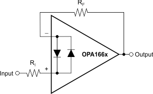
The input terminals of the OPA166x are protected from excessive differential voltage with back-to-back diodes, as Figure 6-2 illustrates. In most circuit applications, the input protection circuitry has no consequence. However, in low-gain or G = +1 circuits, fast ramping input signals can forward bias these diodes because the output of the amplifier cannot respond rapidly enough to the input ramp. If the input signal is fast enough to create this forward bias condition, the input signal current must be limited to 10mA or less. If the input signal current is not inherently limited, an input series resistor (RI), a feedback resistor (RF), or both, can be used to limit the signal input current. This resistor degrades the low-noise performance of the OPA166x and is examined in Section 6.1.3. Figure 6-2 shows an example configuration when both current-limiting input and feedback resistors are used.
 Figure 6-2 Pulsed Operation