JAJSEA5D December   2017  – October 2019 OPA207

PRODUCTION DATA.  

  1. 特長
  2. アプリケーション
  3. 概要
    1.     Device Images
      1.      非常に低い0.1Hz~10Hzのノイズ
  4. 改訂履歴
  5. Pin Configuration and Functions
    1.     Pin Functions
  6. Specifications
    1. 6.1 Absolute Maximum Ratings
    2. 6.2 ESD Ratings
    3. 6.3 Recommended Operating Conditions
    4. 6.4 Thermal Information
    5. 6.5 Electrical Characteristics
    6. 6.6 Typical Characteristics
  7. Detailed Description
    1. 7.1 Overview
    2. 7.2 Functional Block Diagram
    3. 7.3 Feature Description
      1. 7.3.1 Operating Voltage
      2. 7.3.2 Input Protection
      3. 7.3.3 ESD Protection
      4. 7.3.4 Input Stage Linearization
      5. 7.3.5 Rail-to-Rail Output
      6. 7.3.6 Low Input Bias Current
      7. 7.3.7 Slew Boost
      8. 7.3.8 EMI Rejection Ratio (EMIRR)
    4. 7.4 Device Functional Modes
  8. Application and Implementation
    1. 8.1 Application Information
    2. 8.2 Typical Applications
      1. 8.2.1 Typical OPA207 Application
        1. 8.2.1.1 Design Requirements
        2. 8.2.1.2 Detailed Design Procedure
        3. 8.2.1.3 Application Curve
      2. 8.2.2 Precision Low-Side Current Sensing
      3. 8.2.3 Precision Buffer With Increased Output Current
  9. Power Supply Recommendations
  10. 10Layout
    1. 10.1 Layout Guidelines
    2. 10.2 Layout Example
  11. 11デバイスおよびドキュメントのサポート
    1. 11.1 デバイス・サポート
      1. 11.1.1 開発サポート
        1. 11.1.1.1 WEBENCH Filter Designerツール
        2. 11.1.1.2 TINA-TI(無料のダウンロード・ソフトウェア)
        3. 11.1.1.3 TI Precision Designs
    2. 11.2 ドキュメントのサポート
      1. 11.2.1 関連資料
    3. 11.3 ドキュメントの更新通知を受け取る方法
    4. 11.4 サポート・リソース
    5. 11.5 商標
    6. 11.6 静電気放電に関する注意事項
  12. 12メカニカル、パッケージ、および注文情報

パッケージ・オプション

メカニカル・データ(パッケージ|ピン)
サーマルパッド・メカニカル・データ
発注情報

Rail-to-Rail Output

The OPA207 uses a rail-to-rail output stage capable of swinging within a few millivolts from either power supply rail while maintaining high open-loop gain. Figure 40 shows a simplified drawing of the output stage circuit. Resistors connected in series with each output transistor ensure a consistent output current limit. Limiting the output current in this way ensures reliable operation of the OPA207 under short circuited conditions and protects sensitive loads from being damaged by excessive current. Figure 41 and Figure 42 illustrate the maximum output current available from the OPA207 at various temperatures.

OPA207 OPA207_Rail_to_Rail_Output.gifFigure 40. Simplified Rail-to-Rail Output Stage Circuit
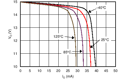
OPA207 C009A_DC.pngFigure 41. Output Swing to Rail While Sourcing Current
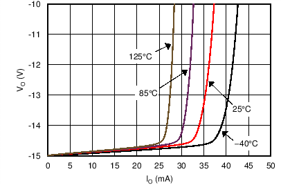
OPA207 C009B_DC.pngFigure 42. Output Swing to Rail While Sinking Current