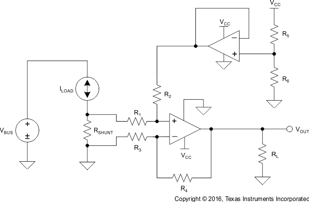
-
OPAx330 50-μV VOS, 0.25-μV/°C, 35-μA CMOS Operational Amplifiers Zero-Drift Series
- 1 Features
- 2 Applications
- 3 Description
- 4 Revision History
- 5 Device Comparison Table
- 6 Pin Configurations and Functions
- 7 Specifications
- 8 Detailed Description
- 9 Application and Implementation
- 10Power Supply Recommendations
- 11Layout
- 12Device and Documentation Support
- 13Mechanical, Packaging, and Orderable Information
- IMPORTANT NOTICE
パッケージ・オプション
デバイスごとのパッケージ図は、PDF版データシートをご参照ください。
メカニカル・データ(パッケージ|ピン)
- D|8
- DGK|8
- DRB|8
サーマルパッド・メカニカル・データ
- DRB|8
発注情報
OPAx330 50-μV VOS, 0.25-μV/°C, 35-μA CMOS Operational Amplifiers Zero-Drift Series
1 Features
2 Applications
3 Description
The OPA330 series of CMOS operational amplifiers offer precision performance at a very competitive price. These devices are members of the Zero-Drift family of amplifiers which use a proprietary auto-calibration technique to simultaneously provide low offset voltage (50-μV maximum) and near-zero drift over time and temperature at only 35 μA (maximum) of quiescent current. The OPA330 family features rail-to-rail input and output in addition to near-flat 1/f noise, making this amplifier ideal for many applications and much easier to design into a system. These devices are optimized for low-voltage operation as low as 1.8 V (±0.9 V) and up to 5.5 V (±2.75 V).
The OPA330 (single version) is available in the 5-pin DSBGA, 5-pin SC70, 5-pin SOT-23, and 8-pin SOIC packages. The OPA2330 (dual version) is offered in 3 mm × 3 mm, 8-pin SON, 8-pin VSSOP, and 8-pin SOIC packages. The OPA4330 is offered in the standard 14-pin SOIC and 14-pin TSSOP packages, as well as in the space-saving 14-pin VQFN package. All versions are specified for operation from –40°C to 125°C.
Device Information(1)
| PART NUMBER | PACKAGE | BODY SIZE (NOM) |
|---|---|---|
| OPA330 | SOIC (8) | 4.90 mm × 3.91 mm |
| SOT (5) | 2.90 mm × 1.60 mm | |
| SC70 (5) | 2.00 mm × 1.25 mm | |
| DSBGA (5) | 0.00 mm × 0.00 mm | |
| OPA2330 | SOIC (8) | 4.90 mm × 3.91 mm |
| VSSOP (8) | 3.00 mm × 3.00 mm | |
| SON (8) | 3.00 mm × 3.00 mm | |
| OPA4330 | SOIC (14) | 8.65 mm × 3.91 mm |
| TSSOP (14) | 5.00 mm × 4.40 mm | |
| VQFN (14) | 3.50 mm × 3.50 mm |
- For all available packages, see the orderable addendum at the end of the data sheet.
4 Revision History
Changes from F Revision (June 2016) to G Revision
- Changed Pin Functions: OPA330 so each pin has a separate rowGo
- Changed position of Input Voltage Range, CMRR parameter specification values in Electrical Characteristics tableGo
- Changed position of Open-Loop Gain, AOL parameter specification values in Electrical Characteristics tableGo
Changes from E Revision (February 2011) to F Revision
- Added ESD Ratings table, Feature Description section, Device Functional Modes, Application and Implementation section, Power Supply Recommendations section, Layout section, Device and Documentation Support section, and Mechanical, Packaging, and Orderable Information section Go
- Added current package designators to second paragraph of Description section Go
- Removed Package Information table, see POA at the end of the datasheetGo
- Changed Product Family Package Comparison table to Device Comparison table; moved from page 1 of documentGo
Changes from D Revision (June 2010) to E Revision
- Changed document status from Mixed Status to Production DataGo
- Deleted footnote 2 from the Package Information tableGo
- Added remaining thermal information dataGo
Changes from C Revision (October 2009) to D Revision
- Added last Applications bulletGo
- Deleted footnote 2 and shading from all packages except QFN-14; moved WCSP-5, SOIC-14, and TSSOP-14 packages to Production Data status; and added package marking information to Package Information tableGo
- Deleted footnote 1 from Product Family Package Comparison tableGo
- Moved TSSOP-14 thermal resistance to MSOP-8, SOIC-8 thermal resistance parameter in Electrical Characteristics tableGo
- Deleted SOIC-14 and QFN-14 rows from Temperature Range section in Electrical Characteristics tableGo
- Added OPA330YFF, OPA4330 Input Bias Current parameter to Electrical Characteristics tableGo
- Added Input Voltage Range, OPA330YFF, OPA4330 Common-Mode Rejection Ratio parameter to Electrical Characteristics tableGo
6 Pin Configurations and Functions
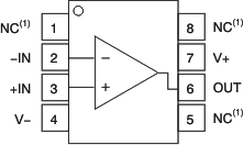
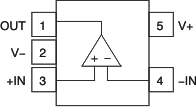
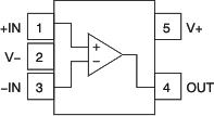
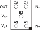
Pin Functions: OPA330
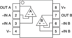
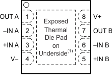
Pin Functions: OPA2330
| PIN | I/O | DESCRIPTION | ||
|---|---|---|---|---|
| NAME | SOIC, VSSOP |
SON | ||
| –IN A | 2 | 2 | I | Negative (inverting) input signal, channel A |
| +IN A | 3 | 3 | I | Positive (noninverting) input signal, channel A |
| –IN B | 6 | 6 | I | Negative (inverting) input signal, channel B |
| +IN B | 5 | 5 | I | Positive (noninverting) input signal, channel B |
| OUT A | 1 | 1 | O | Output channel A |
| OUT B | 7 | 7 | O | Output channel B |
| V– | 4 | 4 | — | Negative (lowest) power supply |
| V+ | 8 | 8 | — | Positive (highest) power supply |
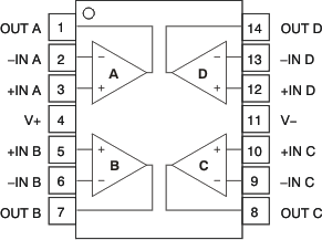
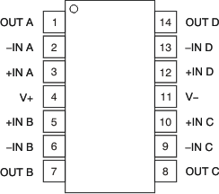
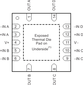
Pin Functions: OPA4330
| PIN | I/O | DESCRIPTION | |||
|---|---|---|---|---|---|
| NAME | SOIC | TSSOP | VQFN | ||
| –IN A | 2 | 2 | 2 | I | Negative (inverting) input signal, channel A |
| +IN A | 3 | 3 | 3 | I | Positive (noninverting) input signal, channel A |
| –IN B | 6 | 6 | 6 | I | Negative (inverting) input signal, channel B |
| +IN B | 5 | 5 | 5 | I | Positive (noninverting) input signal, channel B |
| –IN C | 9 | 9 | 9 | I | Negative (inverting) input signal, channel C |
| +IN C | 10 | 10 | 10 | I | Positive (noninverting) input signal, channel C |
| –IN D | 13 | 13 | 13 | I | Negative (inverting) input signal, channel D |
| +IN D | 12 | 12 | 12 | I | Positive (noninverting) input signal, channel D |
| OUT A | 1 | 1 | 1 | O | Output channel A |
| OUT B | 7 | 7 | 7 | O | Output channel B |
| OUT C | 8 | 8 | 8 | O | Output channel C |
| OUT D | 14 | 14 | 14 | O | Output channel D |
| V– | 11 | 11 | 11 | — | Negative (lowest) power supply |
| V+ | 4 | 4 | 4 | — | Positive (highest) power supply |
