JAJSF79F
March 2002 – April 2018
OPA2357
,
OPA357
PRODUCTION DATA.
1
特長
2
アプリケーション
3
概要
Device Images
概略回路図
4
改訂履歴
5
Pin Configuration and Functions
Pin Functions
6
Specifications
6.1
Absolute Maximum Ratings
6.2
ESD Ratings
6.3
Recommended Operating Conditions
6.4
Thermal Information
6.5
Electrical Characteristics: VS = +2.7-V to +5.5-V Single-Supply
6.6
Typical Characteristics
7
Detailed Description
7.1
Overview
7.2
Functional Block Diagram
7.3
Feature Description
7.3.1
OPAx357 Comparison
7.3.2
Operating Voltage
7.3.3
Enable Function
7.3.4
Rail-to-Rail Input
7.3.5
Rail-to-Rail Output
7.3.6
Output Drive
7.3.7
Video
7.3.8
Wideband Video Multiplexing
7.3.9
Driving Analog-to-Digital Converters
7.3.10
Capacitive Load and Stability
7.3.11
Wideband Transimpedance Amplifier
7.4
Device Functional Modes
8
Application and Implementation
8.1
Application Information
8.2
Typical Applications
8.2.1
Transimpedance Amplifier
8.2.1.1
Design Requirements
8.2.1.2
Detailed Design Procedure
8.2.1.2.1
Custom Design With WEBENCH® Tools
8.2.1.2.2
OPAx357 Design Procedure
8.2.1.2.2.1
Optimizing the Transimpedance Circuit
8.2.1.3
Application Curve
8.2.2
High-Impedance Sensor Interface
8.2.3
Driving ADCs
8.2.4
Active Filter
9
Power Supply Recommendations
9.1
Power Dissipation
10
Layout
10.1
Layout Guidelines
10.2
Layout Example
11
デバイスおよびドキュメントのサポート
11.1
デバイス・サポート
11.1.1
開発サポート
11.1.1.1
WEBENCH®ツールによるカスタム設計
11.2
ドキュメントのサポート
11.2.1
関連資料
11.3
関連リンク
11.4
ドキュメントの更新通知を受け取る方法
11.5
コミュニティ・リソース
11.6
商標
11.7
静電気放電に関する注意事項
11.8
Glossary
12
メカニカル、パッケージ、および注文情報
パッケージ・オプション
メカニカル・データ(パッケージ|ピン)
DBV|6
MPDS026Q
サーマルパッド・メカニカル・データ
発注情報
jajsf79f_oa
jajsf79f_pm
6.6
Typical Characteristics
at T
A
= 25°C, V
S
= 5 V, G = +1, R
F
= 0 Ω, R
L
= 1 kΩ, and connected to V
S
/ 2 (unless otherwise noted)
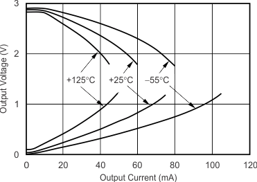
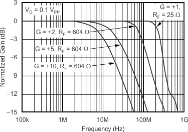
Figure 1.
Noninverting Small-Signal Frequency Response
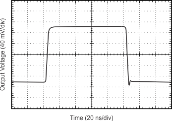
Figure 3.
Noninverting Small-Signal Step Response
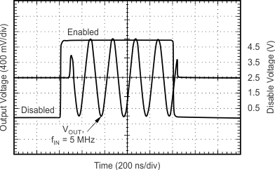
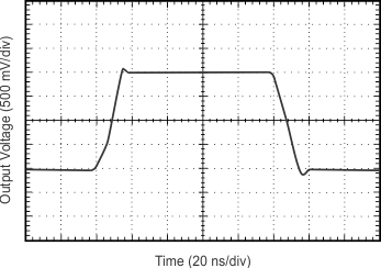
Figure 5.
Large-Signal Disable, Enable Response
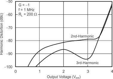
Figure 7.
Harmonic Distortion vs Output Voltage
Figure 9.
Harmonic Distortion vs Inverting Gain
Figure 11.
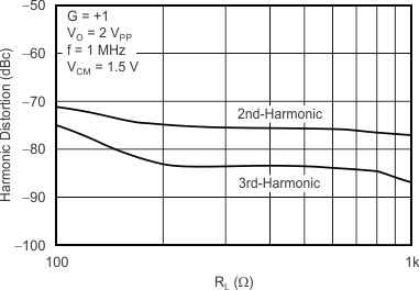
Harmonic Distortion vs Load Resistance
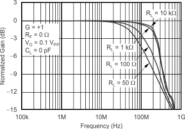
Figure 13.
Frequency Response for Various R
L
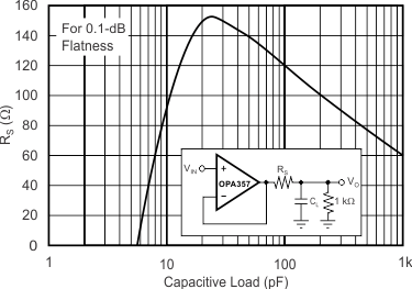
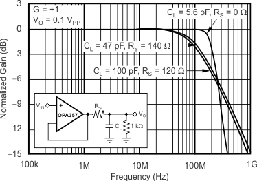
Figure 15.
Recommended R
S
vs Capacitive Load
Figure 17.
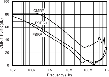
Common-Mode Rejection Ratio and Power-Supply Rejection Ratio vs Frequency
Figure 19.
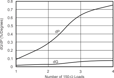
Composite Video differential Gain and Phase
V
S
= 3 V
Figure 21.
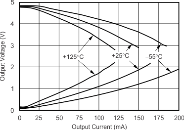
Output Voltage Swing vs Output Current
V
S
= 5 V
Figure 23.
Output Voltage Swing vs Output Current
Figure 25.
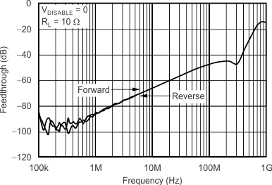
Disable Feedthrough vs Frequency
Figure 27.
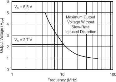
Maximum Output Voltage vs Frequency
Figure 29.
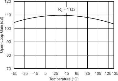
Open-Loop Gain vs Temperature
Figure 31.
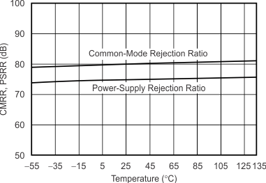
Common-Mode Rejection Ratio and Power-Supply Rejection Ratio vs Temperature
Figure 2.
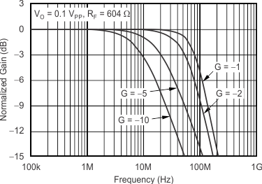
Inverting Small-Signal Frequency Response
Figure 4.
Noninverting Large-Signal Step Response
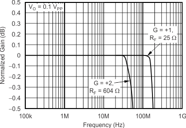
Figure 6.
0.1-dB Gain Flatness
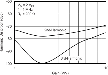
Figure 8.
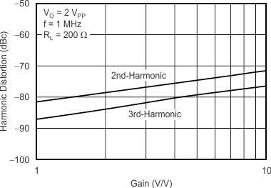
Harmonic Distortion vs Noninverting Gain
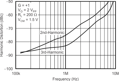
Figure 10.
Harmonic Distortion vs Frequency
Figure 12.
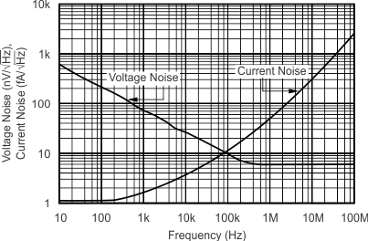
Input Voltage and Current Noise Spectral Density vs Frequency
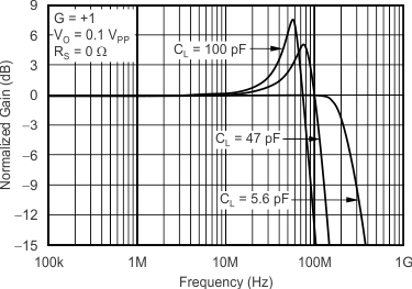
Figure 14.
Frequency Response for Various C
L
Figure 16.
Frequency Response vs Capacitive Load
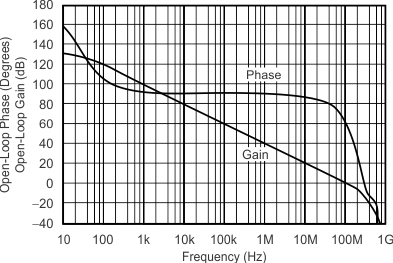
Figure 18.
Open-Loop Gain and Phase
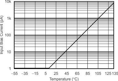
Figure 20.
Input Bias Current vs Temperature
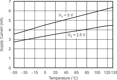
Figure 22.
Supply Current vs Temperature
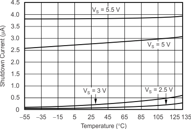
Figure 24.
Shutdown Current vs Temperature
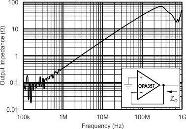
Figure 26.
Closed-Loop Output Impedance vs Frequency
Figure 28.
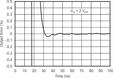
Output Settling Time to 0.1%
Figure 30.
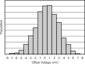
Offset Voltage Production Distribution
Figure 32.
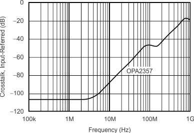
Channel-to-Channel Crosstalk