JAJSKJ3J june 2020 – june 2023 OPA2863 , OPA4863 , OPA863
PRODUCTION DATA
- 1
- 1 特長
- 2 アプリケーション
- 3 概要
- 4 Revision History
- 5 Device Comparison Table
- 6 Pin Configuration and Functions
-
7 Specifications
- 7.1 Absolute Maximum Ratings
- 7.2 ESD Ratings
- 7.3 Recommended Operating Conditions
- 7.4 Thermal Information: OPA863
- 7.5 Thermal Information: OPA2863
- 7.6 Thermal Information: OPA4863
- 7.7 Electrical Characteristics: VS = 10 V
- 7.8 Electrical Characteristics: VS = 3 V
- 7.9 Typical Characteristics: VS = 10 V
- 7.10 Typical Characteristics: VS = 3 V
- 7.11 Typical Characteristics: VS = 3 V to 10 V
- 8 Detailed Description
- 9 Application and Implementation
- 10Device and Documentation Support
- 11Mechanical, Packaging, and Orderable Information
9.2.5 Clamp-On Ultrasonic Flow Meter
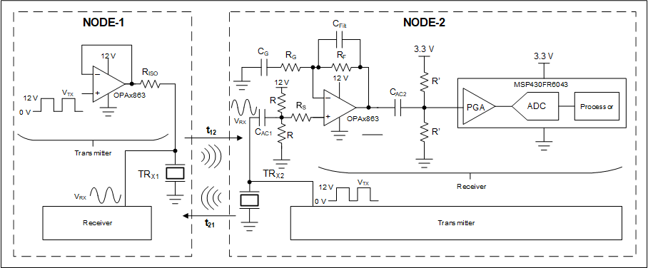
Figure 9-6 shows how ultrasonic flow meters measure the rate of flow of a liquid using transit-time difference (t12–t21), which depends on the flow rate. Figure 9-6 shows a representative schematic for a non-intrusive ultrasonic flow meter using the OPAx863 and 12-V transducer excitation. The OPAx863 are used for the forward path as a unity-gain buffer for 12-V pulsed transducer excitation at NODE 1. At the same time, the receiver circuit at NODE 2 (which also uses the OPAx863) first provides an ac-gain followed by a dc-level shift to lead to the PGA, ADC, and processor within the MSP430™ microcontroller.
NODE 2 and NODE 1 use similar transmit and receive circuits (discussed previously) for the reverse path. The OPAx863 wide GBW of 50 MHz introduces minimal phase-delay and low-noise for excellent flow rate measurement. The amplifier stays in power-down mode for a majority of the time in battery-powered systems. This configuration results in very small average system-level power consumption and prolonged battery lifetime with the 1.5‑µA (maximum) power-down mode quiescent current with a 3-V supply. The transmit and receive signal chains are connected to the same point at the respective node transducers. Therefore, the OPAx863 12.6-V supply voltage capability enables 12-V transducer excitation without any damage to the front-end, or a need for external switches, thus enabling a more compact solution. These specifications make the OPAx863 an excellent choice for flow measurements in large diameter pipes and non-intrusive flow meters. The TIDM-02003 reference design discusses an ultrasonic gas flow sensing subsystem which uses high-speed amplifiers for front-end amplification.
 Figure 9-6 Non-Intrusive Ultrasonic Flow
Meter