-
PCM2912A Audio Codec With USB Interface, Mono Microphone Input and Stereo Headphone Output
- 1 Features
- 2 Applications
- 3 Description
- 4 Revision History
- 5 Device Comparison Table
- 6 Pin Configuration and Functions
-
7 Specifications
- 7.1 Absolute Maximum Ratings
- 7.2 ESD Ratings
- 7.3 Recommended Operating Conditions
- 7.4 Thermal Information
- 7.5 Electrical Characteristics
- 7.6
Typical Characteristics
- 7.6.1 ADC Digital Decimation Filter Frequency Response
- 7.6.2 ADC Digital High-Pass Filter Frequency Response
- 7.6.3 ADC Analog Antialiasing Filter Frequency Response
- 7.6.4 DAC Digital Interpolation Filter Frequency Response
- 7.6.5 DAC Analog FIR Filter Frequency Response
- 7.6.6 DAC Analog Low-Pass Filter Frequency Response
- 7.6.7 ADC
- 7.6.8 DAC
- 7.6.9 Supply Current
- 8 Parameter Measurement Information
-
9 Detailed Description
- 9.1 Overview
- 9.2 Functional Block Diagram
- 9.3 Feature Description
- 9.4 Device Functional Modes
- 9.5 Programming
- 10Application and Implementation
- 11Power Supply Recommendations
- 12Layout
- 13Device and Documentation Support
- 14Mechanical, Packaging, and Orderable Information
- IMPORTANT NOTICE
DATA SHEET
PCM2912A Audio Codec With USB Interface, Mono Microphone Input and Stereo Headphone Output
1 Features
- On-Chip USB Interface:
- With Full-Speed Transceivers
- Fully Compliant With USB 2.0 Specification
- Certified By USB-IF
- Partially Programmable Descriptors
- Adaptive Isochronous Transfer for Playback
- Asynchronous-Isochronous Transfer for Record
- Bus Powered
- 16-Bit Delta-Sigma ADC and DAC
- Sampling Rate:
- 8, 11.025, 16, 22.05, 32, 44.1, or 48 kHz
- On-Chip Clock Generator:
- With Single 6-MHz Clock Source
- Mono ADC with Microphone Input
- Analog Performance at VBUS = 5 V:
- THD+N: 0.01%
- SNR: 92 dB
- Dynamic Range: 90 dB
- Decimation Digital Filter
- Passband Ripple: ±0.05 dB
- Stop-Band Attenuation: –65 dB
- Single-Ended Voltage Input
- Antialiasing Filter Included
- Digital HPF Included
- Microphone Bias, Microphone Amplifier, and Input PGA
- Analog Performance at VBUS = 5 V:
- Stereo DAC With Headphone Output
- Analog Performance at VBUS = 5.0 V:
- THD+N: 0.01% (RL > 10 kΩ)
- THD+N: 0.02% (RL = 32 Ω)
- SNR: 92 dB
- Dynamic Range: 90 dB
- PO: 13 mW (RL = 32 Ω)
- PO: 25 mW (RL = 16 Ω)
- Oversampling Digital Filter
- Passband Ripple: ±0.1 dB
- Stop-Band Attenuation: –43 dB
- Single-Ended Voltage Output
- Analog LPF Included
- Sidetone PGA, Output PGA, and HP Amplifier
- Analog Performance at VBUS = 5.0 V:
- Multifunctions:
- Suspend, Playback, and Record Status Flag
- Microphone Amplifier, Mute, and Gain Control
- Pop/Click Noise-Free
- Single Power-Supply: 5 V Typical (VBUS)
- Package: 32-Pin TQFP
2 Applications
- USB Headset
- USB Headphone
- USB Speaker
- USB Featured Consumer Audio Product
- USB Audio Interface Box
- USB Monitor
- Video Conference System
3 Description
The PCM2912A is the Texas Instruments single-chip, USB stereo audio codec with a USB, 2.0-compliant, full-speed protocol controller and an analog front-end (AFE) function for headset applications.
The USB protocol controller works with no software code, but USB descriptors can be modified on request. The PCM2912A employs SpAct™ architecture, TI’s unique system that recovers the audio clock from USB packet data. On-chip analog PLLs with SpAct enables independent playback and record sampling rates with low clock jitters.
Device Information(1)
| PART NUMBER | PACKAGE | BODY SIZE (NOM) |
|---|---|---|
| PCM2912A | TQFP (32) | 7.00 mm × 7.00 mm |
- For all available packages, see the orderable addendum at the end of the data sheet.
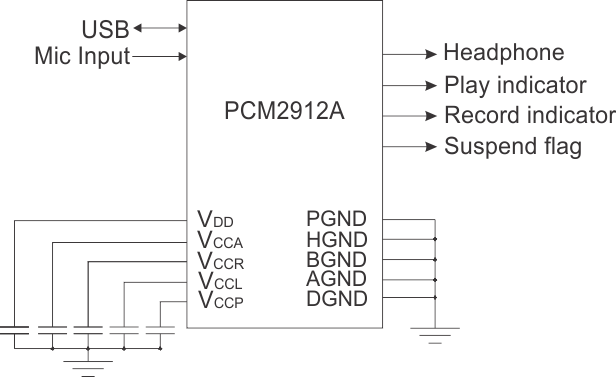
Block Diagram

4 Revision History
Changes from * Revision (September 2008) to A Revision
- Added Pin Configuration and Functions section, ESD Ratings table, Feature Description section, Device Functional Modes, Application and Implementation section, Power Supply Recommendations section, Layout section, Device and Documentation Support section, Device Comparison table, and Mechanical, Packaging, and Orderable Information section Go
5 Device Comparison Table
| FEATURE | PCM2900C | PCM2902C | PCM2903C | PCM2906C | PCM2912A |
|---|---|---|---|---|---|
| Supply voltage | 5 V (Bus-Powered) | 5 V (Bus-Powered) | 3.3 V (Bus-Powered) | 5 V (Bus-Powered) | 5 V (Bus-Powered) |
| Additional features | — | S/PDIF I/O | S/PDIF I/O | S/PDIF I/O 500-mA Maximum Power Configuration |
Mic Bias PGAs Sidetone |
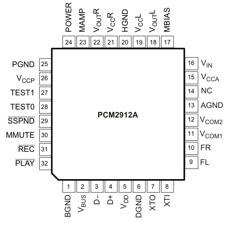
6 Pin Configuration and Functions
PJT Package
32-Pin TQFP
Top View

Pin Functions
| PIN | I/O | DESCRIPTION | |
|---|---|---|---|
| NAME | NO. | ||
| AGND | 13 | — | Analog ground |
| BGND | 1 | — | Reference for internal regulator |
| D– | 3 | I/O | USB differential input/output minus(1) |
| D+ | 4 | I/O | USB differential input/output plus(1) |
| DGND | 6 | Digital ground | |
| FL | 9 | — | External filter pin of L-channel (optional) |
| FR | 10 | — | External filter pin of R-channel (optional) |
| HGND | 20 | — | Analog ground for headphone amplifier |
| MAMP | 23 | I | Microphone preamplifier gain control (LOW: Preamplifier off, HIGH: Preamplifier on = +20 dB)(2) |
| MBIAS | 17 | O | Microphone bias output (0.75 VCCA) |
| MMUTE | 30 | I | Microphone mute control, active HIGH (LOW: Mute off, HIGH: Mute on)(3) |
| NC | 14 | — | Not connected |
| PGND | 25 | — | Analog ground for microphone bias, microphone amplifier, and PGA |
| PLAY | 32 | O | Status output for playback (LOW: Playback, FLASH: Mute on playback, HIGH: Stop)(5) |
| POWER | 24 | I | Power consumption declaration select pin (LOW: 100 mA, HIGH: 500 mA) (2) |
| REC | 31 | O | Status output for record (LOW: Record, FLASH: Mute on recode, HIGH: Stop)(5) |
| SSPND | 29 | O | Suspend flag (LOW: Suspend, HIGH: Operational state) |
| TEST0 | 28 | I | Test pin. Must be set to LOW(2) |
| TEST1 | 27 | I | Test pin. Must be set to HIGH(2) |
| VBUS | 2 | — | Connect to USB power (VBUS) |
| VCCA | 15 | — | Analog power supply |
| VCCL | 19 | — | Analog power supply for headphone amplifier of L-channel(4) |
| VCCP | 26 | — | Analog power supply for PLL(4) |
| VCCR | 21 | — | Analog power supply for headphone amplifier of R-channel(4) |
| VCOM1 | 11 | — | Common voltage for ADC, DAC, and analog front-end (VCCA/2). Decoupling capacitor must be connected to AGND. |
| VCOM2 | 12 | — | Common voltage for headphone (VCCA/2). Decoupling capacitor must be connected to AGND. |
| VDD | 5 | — | Digital power supply(4) |
| VIN | 16 | I | ADC microphone input |
| VOUTL | 18 | O | Headphone output for L-channel |
| VOUTR | 22 | O | Headphone output for R-channel |
| XTI | 8 | I | Crystal oscillator input(2) |
| XTO | 7 | O | Crystal oscillator output |
(1) LV-TTL level
(2) 3.3-V CMOS level input.
(3) 3.3-V CMOS level input with internal pulldown resistor.
(4) Connect decoupling capacitor to corresponding ground.
(5) 5-V tolerant, open-drain.