JAJSKL8E june 2006 – october 2020 SN65LVDS302
PRODUCTION DATA
- 1
- 1 特長
- 2 アプリケーション
- 3 概要
- 4 Revision History
- 5 Pin Configuration and Functions
-
6 Specifications
- 6.1 Absolute Maximum Ratings
- 6.2 ESD Ratings
- 6.3 Recommended Operating Conditions
- 6.4 Thermal Information
- 6.5 Electrical Characteristics
- 6.6 Input Electrical Characteristics
- 6.7 Output Electrical Characteristics
- 6.8 Timing Requirements
- 6.9 Switching Characteristics
- 6.10 Device Power Dissipation
- Typical Characteristics
- 7 Parameter Measurement Information
- 8 Detailed Description
-
9 Application and Implementation
- 9.1
Application Information
- 9.1.1 Application Information
- 9.1.2 Preventing Increased Leakage Currents in Control Inputs
- 9.1.3 Calculation Example: HVGA Display
- 9.1.4 How to Determine Interconnect Skew and Jitter Budget
- 9.1.5 F/S Pin Setting and Connecting the SN65LVDS302 to an LCD Driver
- 9.1.6 How to Determine the LCD Driver Timing Margin
- 9.1.7 Typical Application Frequencies
- 9.2 Typical Applications
- 9.1
Application Information
- 10Power Supply Recommendations
- 11Layout
- 12Device and Documentation Support
- 13Mechanical, Packaging, and Orderable Information
3 概要
SN65LVDS302 レシーバは、FlatLink™3G 準拠のシリアル入力データを 27 のパラレル・データ出力にデシリアライズします。SN65LVDS302 レシーバには、1、2、または 3 つのシリアル入力から 30 ビットをロードする 1 つのシフト・レジスタが含まれており、パリティ・ビットをチェックした後、24 のピクセル・ビットと 3 つの制御ビットをパラレル CMOS 出力にラッチします。パリティ・チェックで正しいパリティが確認された場合、チャネル・パリティ・エラー (CPE) 出力は Low のままです。パリティ・エラーが検出された場合、CPE 出力は高パルスを生成し、データ出力バスは新しく受信したピクセルを無視します。代わりに、最後のデータ・ワードが、別のクロック・サイクルの間、出力バスに保持されます。
製品情報(1)
| 部品番号 | パッケージ | 本体サイズ (公称) |
|---|---|---|
| SN65LVDS302 | nFBGA (80) | 5.00mm × 5.00mm |
(1) 利用可能なパッケージについては、このデータシートの末尾にある注文情報を参照してください。
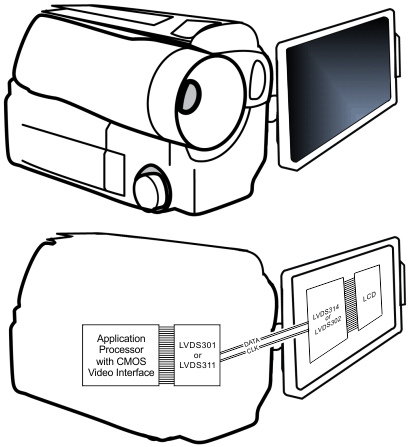
 実装例
実装例