-
TCAN1167-Q1 車載用 CAN FD システム・ベース・チップ、LDO 出力、スリープ・モード、ウォッチドッグ付き
- 1 特長
- 2 アプリケーション
- 3 概要
- 4 Revision History
- 5 概要 (続き)
- 6 Pin Configurations and Functions
- 7 Specifications
- 8 Parameter Measurement Information
-
9 Detailed Description
- 9.1 Overview
- 9.2 Functional Block Diagram
- 9.3
Feature Description
- 9.3.1 VSUP Pin
- 9.3.2 VCCOUT Pin
- 9.3.3 Digital Inputs and Outputs
- 9.3.4 GND
- 9.3.5 INH Pin
- 9.3.6 WAKE Pin
- 9.3.7 nRST Pin
- 9.3.8 SDO
- 9.3.9 nCS Pin
- 9.3.10 SCLK
- 9.3.11 SDI
- 9.3.12 CAN Bus Pins
- 9.3.13 Local Faults
- 9.3.14 Watchdog
- 9.3.15 Bus Fault Detection and Communication
- 9.4 Device Functional Modes
- 9.5
Programming
- 9.5.1 Serial Peripheral Interface (SPI) Communication
- 9.5.2 Serial Clock Input (SCLK)
- 9.5.3 Serial Data Input (SDI)
- 9.5.4 Serial Data Output (SDO)
- 9.5.5 Chip Select Not (nCS)
- 9.5.6
Registers
- 9.5.6.1 DEVICE_ID_y Register (Address = 0h + formula) [reset = xxh]
- 9.5.6.2 REV_ID_MAJOR Register (Address = 8h) [reset = 00h]
- 9.5.6.3 REV_ID_MINOR Register (Address = 9h) [reset = 00h]
- 9.5.6.4 SPI_RSVD_x Register (Address = Ah + formula) [reset = 00h]
- 9.5.6.5 Scratch_Pad_SPI Register (Address = Fh) [reset = 00h]
- 9.5.6.6 MODE_CNTRL Register (Address = 10h) [reset = 04h]
- 9.5.6.7 WD_CONFIG_1 Register (Address = 13h) [reset = 54h]
- 9.5.6.8 WD_CONFIG_2 Register (Address = 14h) [reset = 02h]
- 9.5.6.9 WD_INPUT_TRIG Register (Address = 15h) [reset = 00h]
- 9.5.6.10 WD_QA_CONFIG Register (Address = 2Dh) [reset = 0h]
- 9.5.6.11 WD_QA_ANSWER Register (Address = 2Eh) [reset = 0h]
- 9.5.6.12 WD_QA_QUESTION Register (Address = 2Fh) [reset = 0h]
- 9.5.6.13 STATUS (address = 40h) [reset = 00h]
- 9.5.6.14 INT_GLOBAL Register (Address = 50h) [reset = 0h]
- 9.5.6.15 INT_1 Register (Address = 51h) [reset = 0h]
- 9.5.6.16 INT_2 Register (Address = 52h) [reset = 40h]
- 9.5.6.17 INT_3 Register (Address 53h) [reset = 0h]
- 9.5.6.18 INT_CANBUS Register (Address = 54h) [reset = 0h]
- 9.5.6.19 INT_ENABLE_1 Register (Address = 56h) [reset = F3h]
- 9.5.6.20 INT_ENABLE_2 Register (Address = 57h) [reset = 3Fh]
- 9.5.6.21 INT_ENABLE_3 Register (Address =58h) [reset = 80h]
- 9.5.6.22 INT_ENABLE_CANBUS Register (Address = 59h) [reset = 7Fh]
- 9.5.6.23 INT_RSVD_y Register (Address = 5Ah + formula) [reset = 00h]
- 10Application Information Disclaimer
- 11Power Supply Requirements
- 12Layout
- 13Device and Documentation Support
- 14Mechanical, Packaging, and Orderable Information
- 重要なお知らせ
DATA SHEET
TCAN1167-Q1 車載用 CAN FD システム・ベース・チップ、LDO 出力、スリープ・モード、ウォッチドッグ付き
このリソースの元の言語は英語です。 翻訳は概要を便宜的に提供するもので、自動化ツール (機械翻訳) を使用していることがあり、TI では翻訳の正確性および妥当性につきましては一切保証いたしません。 実際の設計などの前には、ti.com で必ず最新の英語版をご参照くださいますようお願いいたします。
1 特長
- 車載アプリケーション用に AEC Q100 (グレード 1) 認定済み
- ISO 11898-2:2016 の要件に適合
- 機能安全品質管理
- 広い動作入力電圧範囲
- CAN トランシーバ電源用 LDO を内蔵
- 出力電流容量 100mA の 5V LDO
- Classic CAN および 最大 8Mbps の CAN FD
- 各種モードをサポートするウォッチドッグ・タイマ
- タイムアウト
- ウィンドウ
- Q&A ウォッチドッグ
- 各種モードをサポートするウォッチドッグ・タイマ
- 動作モードは SPI からプログラム可能
- 通常モード
- サイレント・モード
- スタンバイ・モード
- 低消費電力スリープ・モード
- システム電源制御のための高電圧 INH 出力
- WAKE ピンによるローカル・ウェイクアップのサポート
- 高度な CAN バス・フォルト検出をサポート
- 電源非接続時の規定された挙動
- バスおよび入出力端子は高インピーダンス (動作中のバスまたはアプリケーションに対して無負荷)
- 保護機能:
- ±58V の CAN バス・フォルト耐性
- VSUP でのロード・ダンプのサポート
- IEC ESD 保護
- 低電圧保護、過電圧保護
- サーマル・シャットダウン保護
- TXD ドミナント状態タイムアウト (TXD DTO)
- きわめて広い接合部温度に対応
- 自動光学検査 (AOI) 性能を向上させたウェッタブル・フランク付きリードレス VSON (14) パッケージで供給
3 概要
TCAN1167-Q1 は、ISO 11898-2:2016 高速 CAN (Controller Area Network) 仕様の物理層要件を満たす高速 CAN SBC (システム・ベーシス・チップ) です。このトランシーバは、Classical CAN ネットワークと最高 8 メガビット/秒 (Mbps) の CAN FD ネットワークの両方に対応しています。
TCAN1167-Q1は、広い入力電源電圧範囲に対応し、5V LDO 出力を内蔵しています。5V LDO 出力 (VCCOUT) は、CAN トランシーバ電圧を内部的に供給し、さらに外部にも電流を供給できます。
TCAN1167-Q1 を使用すると、システムに存在する各種電源供給の有効・無効を INH 出力ピンで切り替えることにより、バッテリの消費電流をシステム・レベルで低減できます。これにより、CAN バスを監視しながら、TCAN1167-Q1 を除くすべてのシステム・コンポーネントの電源が遮断される超低電流スリープ状態を実現します。ウェイクアップ・イベントが検出されると、TCAN1167-Q1 が INH を HIGH に駆動してノードの起動を開始します。
製品情報
| 部品番号 | パッケージ(1) | 本体サイズ (公称) |
|---|---|---|
| TCAN1167-Q1 | VSON (14) | 4.5mm × 3.00mm |
(1) 利用可能なすべてのパッケージについては、このデータシートの末尾にある注文情報を参照してください。
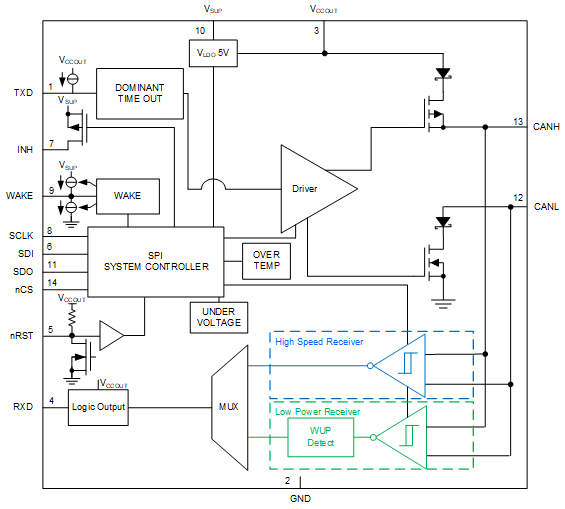
 機能ブロック図