JAJSN47G February 2003 – August 2022 TLC2272-Q1 , TLC2272A-Q1 , TLC2274-Q1 , TLC2274A-Q1
PRODUCTION DATA
- 1 特長
- 2 アプリケーション
- 3 概要
- 4 Revision History
- 5 Pin Configuration and Functions
-
6 Specifications
- 6.1 Absolute Maximum Ratings
- 6.2 ESD Ratings
- 6.3 Recommended Operating Conditions
- 6.4 Thermal Information
- 6.5 Electrical Characteristics: VDD = 5 V (TLC2272-Q1 and TLC2272A-Q1)
- 6.6 Electrical Characteristics: VDD± = ±5 V (TLC2272-Q1 and TLC2272A-Q1)
- 6.7 Electrical Characteristics: VDD = 5 V (TLC2274-Q1 and TLC2274A-Q1)
- 6.8 Electrical Characteristics: VDD± = ±5 V (TLC2274-Q1 and TLC2274A-Q1)
- 6.9 Typical Characteristics
- 7 Detailed Description
- 8 Application and Implementation
- 9 Device and Documentation Support
- 10Mechanical, Packaging, and Orderable Information
パッケージ・オプション
メカニカル・データ(パッケージ|ピン)
サーマルパッド・メカニカル・データ
発注情報
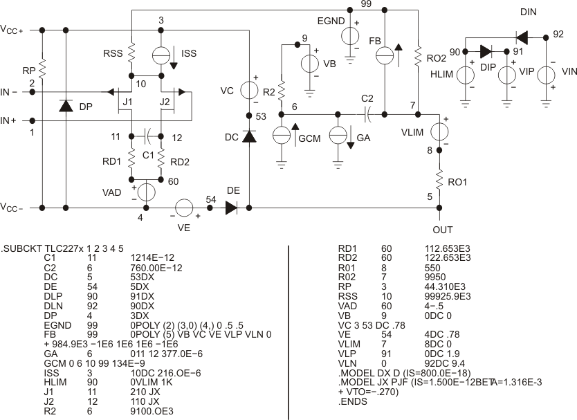
8.1.1 Macromodel Information
Macromodel information provided was derived using MicroSim Parts, the model generation software used with PSpice®. The Boyle macromodel (see also Section 9.2.1) and subcircuit in Figure 8-1 were generated using the TLC227x typical electrical and operating characteristics at TA = 25°C. Using this information, output simulations of the following key parameters can be generated to a tolerance of 20% (in most cases):
|
|
 Figure 8-1 Boyle Macromodels and
Subcircuit