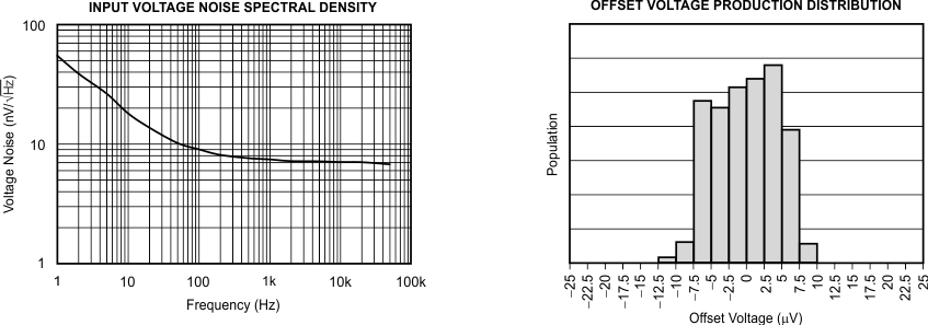
TLVx376ファミリは新世代の低ノイズ・オペアンプで、 e-trim™を搭載し、非常に優れたDC精度とAC特性を実現しています。レール・ツー・レールの入力と出力、低オフセット(最大125μV)、低ノイズ(8nV/√Hz)、静止電流1.2mA (最大値)、5.5MHzの帯域幅と2V/μsの高速なスルー・レートから、このファミリのデバイスは各種の高精度な携帯アプリケーションに非常に魅力的な選択肢です。さらに、これらのデバイスは電源電圧範囲が広く、PSRRが非常に優れているため、バッテリから直接レギュレーションなしで動作するアプリケーションにも理想的です。
TLV376 (シングル・バージョン)はSOT-23-5およびSOIC-8パッケージで供給されます。TLV2376 (デュアル)はVSSOP-8およびSOIC-8パッケージで供給されます。TLV4376 (クワッド)は、TSSOP-14パッケージで供給されます。どのバージョンも、–40°C~+125°Cの動作が保証されています。
型番 | パッケージ | 本体サイズ(公称) |
---|---|---|
TLV376 | SOIC (8) | 4.90mm×3.91mm |
SOT-23 (5) | 2.90mm×1.60mm | |
TLV2376 | SOIC (8) | 4.90mm×3.91mm |
VSSOP (8) | 3.00mm×3.00mm | |
TLV4376 | PW (14) | 5.00mm×4.40mm |
日付 | 改訂内容 | 注 |
---|---|---|
2016年10月 | * | 初版 |
PIN | I/O | DESCRIPTION | ||
---|---|---|---|---|
NAME | DBV | D | ||
–IN | 4 | 2 | I | Negative input signal |
+IN | 3 | 3 | I | Positive input signal |
NC | — | 1, 5, 8 | — | No connection |
OUT | 1 | 6 | O | Output signal |
V– | 2 | 4 | — | Negative supply voltage |
V+ | 5 | 7 | — | Positive supply voltage |
PIN | I/O | DESCRIPTION | ||
---|---|---|---|---|
NAME | D, DGK | |||
–IN A | 2 | I | Inverting input, channel A | |
–IN B | 6 | I | Inverting input, channel B | |
+IN A | 3 | I | Noninverting input, channel A | |
+IN B | 5 | I | Noninverting input, channel B | |
OUT A | 1 | O | Output, channel A | |
OUT B | 7 | O | Output, channel B | |
V– | 4 | — | Negative supply voltage | |
V+ | 8 | — | Positive supply voltage |
PIN | I/O | DESCRIPTION | |
---|---|---|---|
NAME | PW | ||
–IN A | 2 | O | Inverting input, channel A |
–IN B | 6 | O | Inverting input, channel B |
–IN C | 9 | O | Inverting input, channel C |
–IN D | 13 | O | Inverting input, channel D |
+IN A | 3 | I | Noninverting input, channel A |
+IN B | 5 | I | Noninverting input, channel B |
+IN C | 10 | I | Noninverting input, channel C |
+IN D | 12 | I | Noninverting input, channel D |
OUT A | 1 | O | Output, channel A |
OUT B | 7 | O | Output, channel B |
OUT C | 8 | O | Output, channel C |
OUT D | 14 | O | Output, channel D |
V– | 11 | — | Negative supply voltage |
V+ | 4 | — | Positive supply voltage |
MIN | MAX | UNIT | ||
---|---|---|---|---|
Voltage | Supply, VS = (V+) – (V–) | 7 | V | |
Signal input pin(2) | (V–) – 0.5 | (V+) + 0.5 | V | |
Current | Signal input pin(2) | –10 | 10 | mA |
Output short-circuit(3) | Continuous | |||
Temperature | Specified, TA | –40 | 125 | °C |
Junction, TJ | 150 | |||
Storage, Tstg | –65 | 150 |
VALUE | UNIT | |||
---|---|---|---|---|
V(ESD) | Electrostatic discharge | Human body model (HBM), per ANSI/ESDA/JEDEC JS-001(1) | ±4000 | V |
Charged device model (CDM), per JEDEC specification JESD22-C101(2) | ±1000 |
MIN | NOM | MAX | UNIT | |||
---|---|---|---|---|---|---|
Supply voltage, VS = (V+) – (V–) | Single supply | 2.2 | 5.5 | V | ||
Dual supply | ±1.1 | ±2.75 | ||||
TA | Specified temperature range | –40 | 125 | °C |
THERMAL METRIC(1) | TLV376 | UNIT | ||
---|---|---|---|---|
D (SOIC) | DBV (SOT-23) | |||
8 PINS | 5 PINS | |||
RθJA | Junction-to-ambient thermal resistance | 100.1 | 273.8 | °C/W |
RθJC(top) | Junction-to-case (top) thermal resistance | 42.4 | 126.8 | °C/W |
RθJB | Junction-to-board thermal resistance | 41.0 | 85.9 | °C/W |
ψJT | Junction-to-top characterization parameter | 4.8 | 10.9 | °C/W |
ψJB | Junction-to-board characterization parameter | 40.3 | 84.9 | °C/W |
RθJC(bot) | Junction-to-case (bottom) thermal resistance | n/a | n/a | °C/W |
THERMAL METRIC(1) | TLV2376 | UNIT | ||
---|---|---|---|---|
D (SOIC) | DGK (VSSOP) | |||
8 PINS | 8 PINS | |||
RθJA | Junction-to-ambient thermal resistance | 111.1 | 171.2 | °C/W |
RθJC(top) | Junction-to-case (top) thermal resistance | 54.7 | 63.9 | °C/W |
RθJB | Junction-to-board thermal resistance | 51.7 | 92.8 | °C/W |
ψJT | Junction-to-top characterization parameter | 10.5 | 9.2 | °C/W |
ψJB | Junction-to-board characterization parameter | 51.2 | 91.2 | °C/W |
RθJC(bot) | Junction-to-case (bottom) thermal resistance | n/a | n/a | °C/W |
THERMAL METRIC(1) | TLV4376 | UNIT | |
---|---|---|---|
PW (TSSOP) | |||
14 PINS | |||
RθJA | Junction-to-ambient thermal resistance | 107.8 | °C/W |
RθJC(top) | Junction-to-case (top) thermal resistance | 29.6 | °C/W |
RθJB | Junction-to-board thermal resistance | 52.6 | °C/W |
ψJT | Junction-to-top characterization parameter | 1.5 | °C/W |
ψJB | Junction-to-board characterization parameter | 51.6 | °C/W |
RθJC(bot) | Junction-to-case (bottom) thermal resistance | n/a | °C/W |
PARAMETER | TEST CONDITIONS | MIN | TYP | MAX | UNIT | ||
---|---|---|---|---|---|---|---|
OFFSET VOLTAGE | |||||||
VOS | Input offset voltage | TLV376, TLV2376 | 40 | 100 | µV | ||
TLV4376 | 50 | 125 | |||||
dVOS/dT | Offset voltage vs temperature | TA = –40°C to +125°C | 1.0 | μV/°C | |||
PSRR | Power-supply rejection ratio | VS = 2.2 V to 5.5 V, VCM < (V+) – 1.3 V | 84 | 110 | dB | ||
Channel separation, dc | TLV2376, TLV4376 | 0.5 | mV/V | ||||
INPUT BIAS CURRENT | |||||||
IB | Input bias current | 0.3 | pA | ||||
TA = –40°C to +125°C | See Typical Characteristics | ||||||
IOS | Input offset current | 0.2 | pA | ||||
NOISE | |||||||
Input voltage noise | f = 0.1 Hz to 10 Hz | 2.2 | µVPP | ||||
en | Input voltage noise density | f = 1 kHz | 8.0 | nV/√Hz | |||
in | Input current noise | f = 1 kHz | 2 | fA/√Hz | |||
INPUT VOLTAGE RANGE | |||||||
VCM | Common-mode voltage range | (V–) – 0.1 | (V+) + 0.1 | V | |||
CMRR | Common-mode rejection ratio | (V–) < VCM < (V+) – 1.3 V | 72 | 88 | dB | ||
INPUT CAPACITANCE | |||||||
Differential | 6.5 | pF | |||||
Common-mode | 13 | pF | |||||
OPEN-LOOP GAIN | |||||||
AOL | Open-loop voltage gain | 100 mV < VO < (V+) – 100 mV, RL = 2 kΩ | 100 | 126 | dB | ||
FREQUENCY RESPONSE (CL = 100 pF, VS = 5.5 V) | |||||||
GBW | Gain-bandwidth product | 5.5 | MHz | ||||
SR | Slew rate | G = 1 | 2 | V/µs | |||
tS | Settling time | To 0.1%, 2-V step , G = 1 | 1.6 | µs | |||
To 0.01%, 2-V step , G = 1 | 2 | ||||||
Overload recovery time | VIN × gain > VS | 0.33 | μs | ||||
THD+N | Total harmonic distortion + noise | VO = 1 VRMS, G = 1, f = 1 kHz, RL = 10 kΩ | 0.0005% | ||||
OUTPUT | |||||||
Voltage output swing from rail | RL = 10 kΩ | 10 | 20 | mV | |||
ISC | Short-circuit current | Sourcing | 30 | mA | |||
Sinking | –50 | ||||||
CLOAD | Capacitive load drive | See Typical Characteristics | |||||
RO | Open-loop output impedance | 150 | Ω | ||||
POWER SUPPLY | |||||||
VS | Specified voltage range | 2.2 | 5.5 | V | |||
Operating voltage range | 2 to 5.5 | V | |||||
IQ | Quiescent current per amplifier | IO = 0 mA, VS = 5.5 V, VCM < (V+) – 1.3 V | 815 | 1200 | μA | ||
TEMPERATURE | |||||||
Specified range | –40 | 125 | °C |
G = +1 V/V, RL = 10 kΩ, CL = 50 pF |
VS = 5 V, VCM = 2 V, VOUT = 1 VRMS |
VS = ±2.75 V |
VS = ±2.75 V |
G = +1 V/V, RL = 2 kΩ, CL = 50 pF |